CABINET REEL WITH DISPLAY KEYPAD OPERATING INSTRUCTIONS RAPID-AIR CORPORATION 4601 KISHWAUKEE ST. • ROCKFORD, IL 61109-2925 Phone: (815) 397-2578 • Fax: (815) 398-3887 • Web Site: www.rapidair.
OPERATING INSTRUCTIONS CABINET REEL (Revision) 1/8/2002 INSTALLATION 1. The machine that you have just received is fully assembled and ready to be put into position. Due to shipment vibration the machine should be checked to be sure all screws and bolts are tight and that all electrical components are in place inside cabinet. Visually inspect the machine for damaged parts due to shipment. If the machine was damaged in shipment, contact the carrier first to report the damage, and then Rapid-Air. 2.
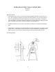
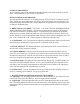
The main control unit is located behind the pushbutton cover. Below is an illustration of the layout of the control panel. This diagram lists all the components and the approximate location of each that could be used for troubleshooting the machine if a problem should occur. The reel is shipped with—120 VAC (1 phase) input. Visually check all electrics before starting the reel.
Mechanical Operating Procedure To Load or Unload a Coil Ring A) If your reel has a fixed center shaft go to Step - 1 B) If your reel has an adjustable center shaft go to Step - 2 Step 1: Release and remove the outer coil retainer from the shaft. Load or unload the coil ring. Replace and secure the outer coil retainer. The reel is now ready for production. Step 2: Release and remove the outer coil retainer from the shaft. If unloading, adjust the centering arms to a position that they have released the coil.
The next screen asks you to set the low set point. If the dancer arm is at “No Material Rest” then just save the setting by pushing the Stop/Run Jog pushbutton. _________________________________ | SENSOR LOW SETPOINT | | SAVE XXX | |_________________________________| The next screen is for setting the high set point. Raise the dancer arm to its upper stop position and press the save or Stop/Run /Jog button once.
DANCER ARM LOOP HEIGHT ADJUSTMENT Eight different loop sensing arm operating positions can be selected during set-up. The material thickness determines the dancer arm rest position. Once the material is threaded up and the dancer arm is resting on the material and the reel runs in the rest position then select a higher number on the height adjustment until the reel stops rotating.
START UP PROCEDURE Prior to applying power to the machine the operator should review all the controls on the machine. A brief summary of the controls is listed below. MAIN CONSOLE & CONTROLLER The main pushbutton control box is mounted on the top of the reel frame. Located on the face of the console are eleven pushbuttons, one display, one on/off switch, one circuit breaker, one external loop plug and inside the box is motor board and one potentiometer when required, all of which are explained below. 1.
. LOOP ARM/EXTERNAL SWITCH This switch selects either dancer arm (internal) by displaying “LV” for loop arm vertical reel or “LH” for loop arm horizontal reel (PMD) or external loop control by displaying “RT” for the RTB and ”RS” for the RS_1. The RLL will work on the “RT” selection. 9. RESET BUTTONS A. 15 amp - This is the main circuit breaker for the reel. 10. REMOTE INTERFACE PORT “D” CONNECTOR This connector is used to communicate with external loop control equipment.
REEL SPECIFICATIONS AND MAINTAINCE CAPACITY SERIES COIL CAPACITY STANDARD STOCK WIDTH MAX COIL O.D. 20 75 LBS 4” 18” 24” 30” 30 150 LBS 4” 24” 30” 36” 40 250 LBS 6” 30” 36” 50 500 LBS 6” 36” 48” ELECTRIC MOTORS R20 to R30 are furnished with 1/4 hp, 2500 rpm permanent magnet D.C. motors. R45 to R58 are furnished with 1/2 hp, 2500 rpm permanent magnet D.C. motors. All motors are 90 V.D.C. unless otherwise specified. All brushes on the motors should be checked every 1500 to 2000 hours.
TROUBLE SHOOTING GUIDE MAIN SWITCH ON BUT NOT LIT 1. CB tripped a. Reset CB 2. Unit not plugged into main power. a. Plug into main power source. 3. No power in incoming line. a. Check outlet. b. Check power cord. 4. Loose wiring a. Check terminals and connections. MOTOR CREEPS IN STOP POSITION 1. “Min” speed pot on RAMM board out of adjustment. UNIT TURNS BUT WON’T JOG 1. Jog function was not selected a. Select jog. 2. Jog speed has not been set up a. Call factory. UNIT ON BUT MOTOR WON’T RUN.
5. Percent speed function set too low. a. Adjust percent speed function to 100%. 6. Fuses blown. a. Check fuses & circuit breaker. 7. No AC voltage at DC drive board. a. Check wiring. 8. Check Signal voltage between P2 to P1 on DC drive. 0-6 VDC—Ramm 0-9 VDC—Regen Drive while moving dancer arm. a. If there is a signal, check continuity between I1 & I2. If no continuity, replace D.C. drive or call factory. 10. Check pico fuse on 69100804 board (F1). a. Replace fuse, 1 amp pico fuse—call factory.
RAPID-AIR CORPORATION RAMM SOLID STATE DC MOTOR SPEED CONTROL SAFETY WARNING—PLEASE READ CAREFULLY This product should be installed and serviced by a qualified technician, electrician or electrical maintenance personnel familiar with its operation and the hazards involved.
PLUG IN HORSEPOWER RESISTOR A Plug-In Horsepower Resistor must be installed to match the RAMM to the motor horsepower and voltage. See table 2 for the correct value. Plug-In Horsepower Resistors are stocked by your distributor. TABLE 2. PLUG IN HORSEPOWER RESISTOR CHART* MOTOR HORSEPOWER RANGE ** Armature Voltage 90-130 VDC Armature Voltage 180 VDC Plug-in Horsepower Resistor Resistance Rapid-Air Value (ohms) P/N 1/4 1/2 3/4 1*** 1/2 1 1-1/2 2*** .05 .025 .015 .
INTRODUCTION The RAMM Full Wave Solid State DC Motor Speed Control represents the latest state of the art design achievable through modern technology. Features Include: Integrated Circuitry Used to control and amplify command and reference levels with both closed and open loop feedback to provide superior motor regulation. (Speed changes due to load, line voltage, or temperature variations are held to minimum levels). High Quality Components Selected and tested for proven dependability.
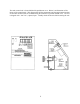
Fig. 1. Basic RAMM Connection Diagram CAUTION: Do not bundle potentiometer connections (P1, P2, P3) and inhibit connections (I1, I2) with AC line or motor wires. B. VOLTAGE FOLLOWING. All models can be controlled with an isolated analog reference voltage (0-6VDC) in lieu of the main speed potentiometer. The voltage is connected to P2 (+) and F-. The control output voltage will linearly follow the input voltage. The source impedance of the input should be 10K ohms or less.
1. AC Line Fuse is chosen according to the maximum rating of the control: 12 AMP fuse for all motors up to 3/4 HP-90V and 1 1/2 HP-180VDC. 25 AMP fuse for all motors 1 and 1 1/2 HP-90v and 2 and 3 HP-180VDC. (Use Buss ABC, Little fuse 326 ceramic fuse or equivalent.) 2. Armature Fuse can be chosen in accordance with the fuse chart. Note: The armature fuse is calculated based on the approximate full load DC current rating of the motor times a from factor of 1.5.
NOTE: In order for the IR comp and CL trim pot settings to be correct, the proper Plug-in Horsepower Resistor must be installed for the particular motor and input volt age being used. Do not attempt to change the settings of the trim pots unless absolutely necessary since they are factory adjusted to near optimum settings. The following procedure, presented in order of adjustment sequence, should be used when readjusting all trim pot functions. Fig 2. ACCEL/DECEL TRIMPOT ADJUSTMENT A. Acceleration Start.
To set the CL to factory specifications adjust as follows: 1. Set speed control knob at approximately 30-50% CW rotation. Set CL trim pot to full CCW position. 2. Connect a DC ammeter in series with the armature lead. 3. Lock shaft of motor (be sure CL pot is in full CCW position). Apply power and rotate CL pot CW slowly until DC ammeter reads 1.5 times motor rating (do not exceed 2 times motor rating, Max. CW position.
LIMITED WARRANTY—RAMM 125, 225, 225D For a period of one (1) year from date of original purchase Rapid-Air Corporation will repair or replace without charge devices which our examination proves to be defective in material or workmanship. This warranty is valid if the unit has not been tampered with by unauthorized persons, misused, abused or improperly installed and has been used in accordance with the instructions and/or ratings supplied.