CABINET REEL OPERATING INSTRUCTIONS MODELS 15, 25, 40 & 60 SERIES RAPID-AIR CORPORATION 4601 KISHWAUKEE ST. • ROCKFORD, IL 61109-2925 Phone: (815) 397-2578 • Fax: (815) 398-3887 • Web Site: www.rapidair.
REEL MANUAL INDEX 1. Installation 2. Reel diagram 3. Reel electric component diagrams for series 15, 25, 40 & 60 4. Reel specifications and maintenance chart 5. Dancer arm functions and diagrams 6. Taut stock functions and diagram 7. Coil load and unload 8. Trouble shooting 9. RAMM motor drive board operating instructions 10. KBRG motor board operating instructions 11.
OPERATING INSTRUCTIONS FOR CABINET REEL SERIES 15, 25, 40, 60 INSTALLATION 1. The reel that you have just received is fully assembled and ready to be put into position. Due to shipment vibration, the reel should be checked to be sure that all screws and bolts are tight and that all electrical components are in place inside the cabinet; visually inspect the reel for damaged parts due to shipment. If the reel was damaged in shipment, contact the carrier first to report the damage and then your distributor. 2.
START UP PROCEDURE Prior to applying power to the machine the operator should review all the controls on the machine. A brief summary of the controls is listed below. MAIN CONSOLE & CONTROLLER The main control console & controls are mounted on the end of the cabinet. Located on the face of the console are eight switches, on potentiometer, push-button and 2 reset switches, which are explained below. 1.
9. LOOP ARM/ARM EXTERNAL SWITCH This switch selects either dancer arm (internal ) or “D” connector (external) speed control functions. 10. RESET BUTTONS a. 15 amp - This is the main circuit breaker for the reel. b. 3 amp - this is the circuit protection for the “D” connector. Any shorts or over loads would trip this breaker. 11. REMOTE INTERFACE PORT “D” CONNECTOR This connector is used to communicate with external loop control equipment.
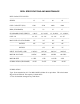
REEL SPECIFICATIONS AND MAINTENANCE REEL CAPACITY VALUES ----------------------------------------------------------------------------------------------------------------SERIES 15 25 40 60 -----------------------------------------------------------------------------------------------------------------COIL CAPACITY (LB.
REEL DANCER ARM FUNCTIONS All the reels manufactured by Rapid-Air have the capability of being run by proportional control {dancer arm} or non-contact loop control {electronic loop sensing}. We designed the electrical circuit so that a switch, mounted on the operator control panel, can be selected to designate internal or external control. If the internal was selected and the reel was in the “payout” mode then the dancer arm would provide the means of controlling the speed of the reel.
cycles. The percent speed potentiometer should have it’s final settings set when the coil is at it’s lowest point before running out of material. When a new coil is then put on the reel, the reel will run somewhat on and off until the coil becomes smaller. The reel speed will then even out until it is running continuously again. The previous example will work only if the same feed length and coil O.D. is repeated for the conditions that the reel was set up for. If a different coil O.D.
TO LOAD OR UNLOAD A COIL The Rapid Air reel is manufactured using a three arm mandrel with manual expansion as standard for all models. This coupled with three inner keeper arms or one inner coil plate and three outer keeper arms complete the coil retaining capabilities. The mandrel adjustment is accomplished by turning a crank handle located on the outer end of the mandrel.
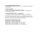
TROUBLE SHOOTING GUIDE MAIN SWITCH ON BUT NOT LIT 1. CB tripped a. Reset CB 2. Unit not plugged into main power a. Plug into main power source 3. No power in incoming line. a. Check outlet. b. Check power cord. 4. Loose wiring a. Check terminals and connections. MOTOR CREEPS IN STOP POSITION 1. R1 & R3 pot on 69100034 board not correctly adjusted. a. Reajust pots so table stops. Call factory. 2. Dancer arm bent. a. Readjust R1 & R3 on 61000033 board. b. Straighten dancer arm. UNIT TURNS ON BUT WON”T JOG 1.
6. Fuses blown. a. Check fuses & circuit breaker. 7. No AC voltage at DC drive board. a. Check wiring. 8. Check signal voltage between P2 to I2 on DC drive. 0-6 VDC - Ramm 0-9 VDC - Regen Drive While moving the dancer arm. a. If there is a signal, check continuity between I1 & I2 If no continuity, replace D.C. drive or call factory. 9. Check line voltage input of 69100033 board, 120 VAC, TB-1. a. Check wiring. Call factory. 10. Check pico fuse 6910033 board (f1). a.
69100034 TAUT STOCK OUTPUT The 69100034 - proportional control board has a taut stock output. This output must be wired to a solid state relay as the Max current draw is 20 ma. The solid state relay’s contact can then be incorporated into the electrical control circuitry. The output can be wired so that the relay is either on or off with the dancer arm down. When the dancer arm reaches the set point for taut stock, the relay switches state.