
User Manual
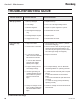
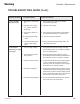
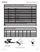

TROUBLESHOOTING GUIDE (Cont.)
General Problem
Possible Causes
Corrective Action
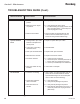
No Turbine Air
Speed Feedback
Fault
No Fluid Flow
1. Turbine drive air not
present
2. Bearing air return signal
not present
3. Brake air is activated
1. Damaged ber optic cable
between robot plate and
control panel
2. Connection at mounting
manifold is loose
3. Fiber optic transmitter failure
4. Bad transceiver module
5. Excessive vibration
6. Fiber optic cable not fully
installed
1. Turbine is not rotating
2. System uid regulator
does not actuate
3. Fluid valve does not
actuate
1. Verify supply air pressure.
2. a. Verify bearing air return signal.
b. Increase bearing air supply pressure to 90
psig (±10 psig) (620.5 +/- 68.9 kPa) mini-
mum 60 psig (413.7 kPa).
3. Remove brake air signal (turbine air and
brake air must be interlocked to prevent
both from being used simultaneously).
1. Repair or replace ber optic cable.
2. Reinstall cable.
3. Replace ber optic transmitter.
4. Replace transceiver module.
5. a. Check bell cup for damage.
b.
Check bell cup for excessive paint build
-up.
c. Ensure bell cup is tightenend properly.
d.
Check cup and shaft tapers for cleanli
ness.
6. Insert cable to full depth.
1. Verify rotation of turbine (the paint valve air
pilot must be interlocked with the turbine
speed feedback signal to ensure that paint
does not ow into the air bearing).
2. a. Verify uid supply.
b. Verify that iar pilot signal is present.
3. a. Verify that air pilot signal is present.
b. Fluid valve air pilot pressure is too low. In-
crease air pressure to 70 psig minimum
(482.6 kPa).
(Continued On Next Page)
Aerobell - Maintenance
61
LN-9264-08.2
Ransburg