
User Manual
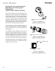
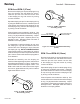
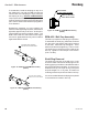
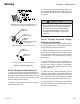
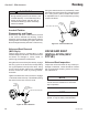
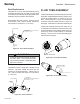
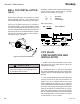
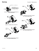
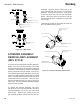
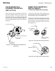

Figure 26b: Fluid Tube Assembly
Seat Replacement
Lubricate the o-ring on the seat assembly using
a suitable lubricant, then by hand, using the seat
removal tool (A10766-00), carefully start the seat
assembly into the pocket of the manifold.
Hand tighten the seat in place. Using a torque
wrench with a 3/8" (10mm) socket, torque the
valve seats to 15-20 lbs•in (1.7-2.3 Nm).
Figure 24: Valve Seat Installation
Figure 25: Valve Installation
> Always use a torque wrench to torque
the sets in place. Over-torquing the sets
may cause permanent unrepairable dam-
age to the manifold.
Lubricate the valve o-rings with a suitable o-ring
lubricant. By hand, thread the valve into the
pocket in a clockwise direction. Tighten using a
1/2" (13mm) socket and torque to 15-20 lbs•in
(1.7-2.3 Nm).
FLUID TUBE ASSEMBLY
Insert uid tube into the turbine body bore from the
back side. Install and tighten the four (4) SSF-3137
screws to a nal torque of 7-10 lbs•in (0.79-1.13
Nm). Install 79001-05 o-ring on to the exposed
end of the uid tube. Make sure this o-ring is not
damaged. Leaks will occur if the item is damaged.
Inspect the uid tube outlet end to make sure it
is centered in the shaft bore. Mis-alignment may
cause uid tube to touch rotating shaft or bell cup
which may result in turbine failure or uid tube
damage. If tube is bent or otherwise damaged,
replace with a new part.
Figure 26a: Fluid Tube Assembly
C A U T I O N
!
TORQUE WRENCH
TIGHTEN VALVE SEAT TO A FINAL TORQUE OF
15-20 LBS/IN (1.7-2.3 Nm)
3/8 INCH SOCKET
A10756-00
VALVE SEAT
TOOL
TORQUE WRENCH
TIGHTEN VALVES TO A FINAL TORQUE OF
15-20 LBS/IN (1.7-2.3 Nm)
A11922-00
VALVE
TOOL
1/2 INCH SOCKET
FLUID TUBE CENTERED
RPM-439 1/8 I.D. (3.18MM)
RPM-440 3/32 I.D. (2.36MM)
RPM-441 1/16 I.D. (1.57MM)
FLUID TUBE
79001-05
O-RING
SSF-3137
SCREW
TORQUE TO 7-10 LBS/IN. (0.79-1.3 Nm)
Aerobell - Maintenance
52
LN-9264-08.2
Ransburg