
User Manual

AIR CONNECTIONS
Brake Air
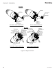
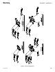
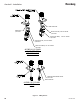
(See Figures 5, 6, and 7 for tubing connections
and sizes.)
> Do not use tape or pipe dope on any air
ttings beyond the nal air lter for BEAR-
ING AIR. The tape or dope may break
free and cause plugging of the turbine air
bearings, and result in turbine failure.
> Provisions should also be made to assure
bearing air remains on during the coast down
period when turbine air is turned off. See
“Specications” in the "Introduction" section
of this manual.
> Brake air is used to slow the turbine
when changing speed. It is recommended
that the brake air and turbine drive air be
interlocked.
NOTE
> If the coating material used is heated,
check the maximum rated temperature for
the uid tubing to be used. Polyethylene
tubing (H-2338 and H-2339) is rated for a
maximum of 80
o
F (27
o
C). Nylon tubing
(H-2340 and H-2341) is rated for 200
o
F
(95
o
C) maximum.
NOTE
Bearing Air
Use tubing (clear, see-through, nylon, natural) to
connect a properly ltered air source to the bearing
air tting on the manifold. It is recommended to
use tubing (clear, see- through) for bearing air
so that any contamination that gets past the nal
bearing air lter will be apparent. Also refer to the
previous "Caution".
Under the “Operation” section which follows, there
is a "Caution" regarding bearing damage if the
turbine is run while bearing air is off. Since the
turbine must not be operated without rst turning
on bearing air, it is required to provide some
means of assuring the presence of bearing air
before turning the turbine “On.” One method is
by interlocking the turbine drive air to the bearing
air (i.e., with an air piloted valve).
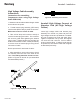
Turbine Air
Turbine drive air must be interlocked with paint ow.
Damage to spindle will occur if paint is triggered
without the bell cup spinning. It is recommended
that the bell cup is spinning at least 10,000 rpm
before any uid is turned on.
FLUID CONNECTIONS
(See Figures 5, 6, and 7 for connections.) See
the following "Note".
> Arcing/re hazard exists if ungrounded
metal connections (air or uid) are used in
the spray area. Use plastic non-conductive
connections, or ensure metal connections are
at ground potential.
W A R N I N G
!
C A U T I O N
!
C A U T I O N
!
Aerobell - Installation
30
LN-9264-08.2
Ransburg