
Manual


LN-9217-00.2
AdaptaFlow Node Adapter - Introduction
INTRODUCTIONINTRODUCTION
INTRODUCTIONINTRODUCTION
INTRODUCTION
GENERAL DESCRIPTIONGENERAL DESCRIPTION
GENERAL DESCRIPTIONGENERAL DESCRIPTION
GENERAL DESCRIPTION
This manual covers the operation and use of the
AdaptaFlow
TM
5000 Node Adapter and is meant to
complement the AdaptaFlow 5000 Fluid Flow
Monitoring and Control Manual.
The AdaptaFlow Node Adapter Module allows for
direct communication from an Allen-Bradley PLC
Remote Input/Output(RIO) port to the AdaptaFlow
5000 Fluid Flow Control system. Up to four
channels of control per half of a standard 19" rack
can be controlled with one Node Adapter Module.
The Node Adapter accepts standard data transfers
from PLC remote I/O and converts the information
to the proper AdaptaFlow protocol for each of the
possible four Channel Cards.
The Node Adapter Module is divided into three
functional blocks: (1)
RIO interfaceRIO interface
RIO interfaceRIO interface
RIO interface, (2)
centralcentral
centralcentral
central
processorprocessor
processorprocessor
processor, and (3)
parallel IO busparallel IO bus
parallel IO busparallel IO bus
parallel IO bus.
The
RIO interfaceRIO interface
RIO interfaceRIO interface
RIO interface contains some Allen-Bradley
components which are licensed to ITW Ransburg.
These are designed specifically to communicate
with the proprietary protocol of the RIO serial link.
The central component of this block is an application
specific IC (ASIC) which is capable of formatting
the RIO information for use by the central
processor(CPU). The actual termination of the
RIO cable is made to the Node Adapter Interface
Board which is connected to the Card Rack Bus
Board.
The core of the
central processorcentral processor
central processorcentral processor
central processor is an 8032
microprocessor which communicates with the
Allen-Bradley ASIC. The 8032 provides an RS-
422 port from which diagnostic functions are
accomplished via internal “debugger” software.
The main software program, which includes the
“debugger” functions, is contained in an Erasable
Programmable Read-Only Memory (EPROM).
The Node Adapter Module communicates to each
AdaptaFlow Channel Card through a digital
parallelparallel
parallelparallel
parallel
IO busIO bus
IO busIO bus
IO bus located on the Card Rack Bus Board.
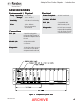
There are two LED indicators located on the front
panel of the Node Adapter Module:
1.
CPUCPU
CPUCPU
CPU - Is on when the microprocessor is
operating normally.
2.
ACTIVEACTIVE
ACTIVEACTIVE
ACTIVE - Is on when communication is
taking place.
The Node Adapter Interface Module is used as a
hardware interface from the PLC remote I/O cable
to the AdaptaFlow card rack. This board is always
required when using the Node Adapter Card. It is
plugged into J6 located on the card rack Bus
Board.
55
55
5
ARCHIVE