
Manual

LN-9217-00.2
AdaptaFlow Node Adapter - Operation
Volts 2 GainVolts 2 Gain
Volts 2 GainVolts 2 Gain
Volts 2 Gain
This parameter is used to scale the spare analog
output. This value acts as a multiplier to the
memory location.
Volts 2 ShifterVolts 2 Shifter
Volts 2 ShifterVolts 2 Shifter
Volts 2 Shifter
This parameter scales the spare analog output. It
acts as a divider to the memory location. For Node
Adapter systems, this parameter should be set to
0.
Volts 2 PointerVolts 2 Pointer
Volts 2 PointerVolts 2 Pointer
Volts 2 Pointer
This parameter specifies which memory location
in the flow controller is mapped to the spare analog
output. After specifying this location, it may be
scaled (Multiplied, Divided or Offset) by three
parameters listed above. For Node Adapter
systems, this parameter should be set to 0.
Volts In OffsetVolts In Offset
Volts In OffsetVolts In Offset
Volts In Offset
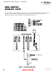
The requested flow rate can be either a hard wired
analog input or programmed via the serial interface.
It should be noted that the hard wired analog input
is always active even when operating in serial
communication mode. The controller will recognize
an input to the hardware analog input terminal if the
voltage exceeds the threshold set up by this
parameter. This is programmed with a value of 0-
4095 which corresponds to a 0-10 VDC threshold.
The Volts In Offset is used in a situation where
there is not an exact 0 VDC at the low point of the
analog input.
Volts In GainVolts In Gain
Volts In GainVolts In Gain
Volts In Gain
This parameter is utilized when the hardware
analog input is used. This value is used to set the
full scale range and represents the maximum flow
rate for the maximum voltage in.
Total Limit 1Total Limit 1
Total Limit 1Total Limit 1
Total Limit 1
This parameter sets the value of the trip point for
flow alarm No. 1. If the value of the totalizer
exceeds this value, the alarm bit is turned on.
Total Limit 2Total Limit 2
Total Limit 2Total Limit 2
Total Limit 2
This parameter sets the value of the trip point for
flow alarm No. 2. If the value of the totalizer
exceeds this value, the alarm bit is turned on.
1616
1616
16
Flow Rate Limit 1Flow Rate Limit 1
Flow Rate Limit 1Flow Rate Limit 1
Flow Rate Limit 1
This parameter sets the value of the trip point for
flow rate alarm No. 1.
Flow Rate Limit 2Flow Rate Limit 2
Flow Rate Limit 2Flow Rate Limit 2
Flow Rate Limit 2
This parameter sets the value of the trip point for
flow rate alarm No. 2.
Controller IDController ID
Controller IDController ID
Controller ID
This parameter is a variable set to identify that a
flow controller has been previously programmed.
It is a 16 bit binary number that may be set to any
value between 0 and ± 32768.
ARCHIVE