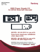
SERVICE MANUAL CP-13-01.1 April — 2013 9060 Power Supply Kit for 80104 External Cascade MODEL: 80143-XXX for use with Esta-Quick Applicator AEMD600 (Atex Approved) MODEL: 80146-XXX for use with Evolver SE (Non-Approved) IMPORTANT: Before using this equipment, carefully read SAFETY PRECAUTIONS, starting on page 1, and all instructions in this manual. Keep this Service Manual for future reference. Service Manual Price: $50.00 (U.S.
CP-13-01.
9060 Power Supply Kit - Contents CONTENTS SAFETY: PAGE 1-6 SAFETY PRECAUTIONS ......................................................................................................... 1 HAZARDS / SAFEGUARDS................................................................................................... 2-6 INTRODUCTION: 8-15 GENERAL DESCRIPTION ........................................................................................................ 8 THE RANSBURG SPRAY PROCESS ........................
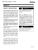
9060 Power Supply Kit - Safety SAFETY SAFETY PRECAUTIONS Before operating, maintaining or servicing any Ransburg electrostatic coating system, read and understand all of the technical and safety literature for your Ransburg products. This manual contains information that is important for you to know and understand. This information relates to USER SAFETY and PREVENTING EQUIPMENT PROBLEMS. To help you recognize this information, we use the following symbols.
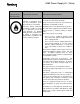
9060 Power Supply Kit - Safety AREA HAZARD SAFEGUARDS Tells where hazards may occur. Tells what the hazard is. Tells how to avoid the hazard. Spray Area Fire Hazard Fire extinguishing equipment must be present in the spray area and tested periodically. Improper or inadequate operation and maintenance proce- Spray areas must be kept clean to prevent the accumulation of combustible residues. dures will cause a fire hazard.
9060 Power Supply Kit - Safety AREA HAZARD SAFEGUARDS Tells where hazards may occur. Tells what the hazard is. Tells how to avoid the hazard. Spray Area Explosion Hazard Electrostatic arcing must be prevented. Safe Improper or inadequate opera- sparking distance must be maintained between the tion and maintenance proce- parts being coated and the applicator. A distance dures will cause a fire hazard. of 1 inch for every 10KV of output voltage is reProtection against inadvertent quired at all times.
9060 Power Supply Kit - Safety AREA HAZARD SAFEGUARDS Tells where hazards may occur. Tells what the hazard is. Tells how to avoid the hazard. Spray Area / High Electrical Discharge Voltage Equipment There is a high voltage device Parts being sprayed and operators in the spray area must be properly grounded. that can induce an electrical charge on ungrounded objects Parts being sprayed must be supported on conveywhich is capable of igniting coat- ors or hangers that are properly grounded.
9060 Power Supply Kit - Safety AREA HAZARD SAFEGUARDS Tells where hazards may occur. Tells what the hazard is. Tells how to avoid the hazard. Electrical Equipment Electrical Discharge High voltage equipment is utilized in the process. Arcing in the vicinity of flammable or combustible materials may occur. Personnel are exposed to high voltage during operation and maintenance.
060 Power Supply Kit - Safety AREA HAZARD SAFEGUARDS Tells where hazards may occur. Tells what the hazard is. Tells how to avoid the hazard. Spray Area Explosion Hazard— Incompatible Materials Halogenated hydrocarbon solvents for example: methylene chloride and 1,1,1,Trichloroethane are not chemically compatible with the aluminum that might be used in many system components. The chemical reaction caused by these solvents reacting with aluminum can become violent and lead to an equipment explosion.
9060 Power Supply Kit - Introduction NOTES 7 CP-13-01.
9060 Power Supply Kit - Introduction INTRODUCTION GENERAL DESCRIPTION The Ransburg Spray Process The Ransburg Spray Process is an air atomized method for applying coatings to objects electrostatically. This system applies a high voltage DC charge to the applicator nozzle electrode, creating an electrostatic field between the atomizer and the target object. The target is electrically grounded through its support that may be either stationary or moving.
9060 Power Supply Kit - Introduction The 9060 Power Supply Kit is available for automatic applicators as follows: **Note: CE/Atex approval with this power source is only for the AEMD-600 **9060 Power Supply Kit Part Structure 80143-ABC (Atex approved when used with AEMD600)-Esta-Quick A-Unit Power Type -1 For 110/120 V Input Power (Domestic) 10” Rack -2 For 220/240 V Input Power (European) 10”Rack -3 For 220/240 V Input Power (Chinese) 10” Rack -4 For 110/120 V Input Power (Domestic) Box Style -5 For 220/
9060 Power Supply Kit - Introduction SPECIFICATIONS Physical - #80143 Kit - 10” Rack 9060 P/N 80120-31X Input: Voltage: 90-264 VAC 429mm (16.9 inches) (483mm ear to ear) (19 inches) Current: 0.4/0.2 Amps AC 308mm (12.1 inches) Wattage: 40 watts (Max.) 6.8 kg (15.1 lbs.) Output: Voltage: 0-10 VRMS Current: 1.5 Amps RMS (max.) Height: 132mm (5.2 inches) Width: Depth: Weight: Physical - #80143 Kit - 19” Box 9060 P/N 80100-31X Height: 16.5 cm (6.5 inches) Width: 37.8 cm (14.
9060 Power Supply Kit - Introduction Number 1 2 3 4 5 6 7 8 9 10 11 12 Description Kilovolt Display Micro Amp Display High Voltage On Indicator Unit—OFF—OFF Switch Set Point Adjust Buttons Fault Indicator Manual Reset Pad External Wiring Grommet Fuse Low Voltage Cable Connector AC Inlet Receptacle Ground Wire Assembly Figure 1: 80100 Cascade Control Unit Features 11 CP-13-01.
9060 Power Supply Kit - Introduction Number 1 2 3 4 5 6 7 8 9 10 11 12 Description Kilovolt Display Micro Amp Display High Voltage On Indicator Unit—OFF—OFF Switch Set Point Adjust Buttons Fault Indicator Manual Reset Pad External Wiring Grommet Fuse Low Voltage Cable Connector AC Inlet Receptacle Ground Wire Assembly Figure 2: 80120 Cascade Control Unit Features CP-13-01.
9060 Power Supply Kit - Introduction Number 1 2 3 4 Description Low Voltage Cable Connector Ground Lug Connector Cascade High Voltage Connection Ground Wire Assembly Figure 3: 80104 Cascade Control Unit Features 13 CP-13-01.
9060 Power Supply Kit - Introduction EUROPEAN ATEX DIRECTIVE 94/9/EC, ANNEX II, 1.0.6 The following instructions apply to equipment covered by certificate number Sira 11ATEX5240X: 8. The certification of this equipment relies upon the following materials used in its construction: 1. The equipment may be used with flammable gases and vapors with apparatus groups II and with temperature class T6.
9060 Power Supply Kit - Installation 9060 Cascade Low Voltage Control Unit Kit ATEX Product 80143-XXX Marking Definitions Ex Certificate Number: Sira 11ATEX5240X Sira = Notified Body performing EC-type examination 11 = Year of certification ATEX = Reference to ATEX Directive 5 = Protection Concept Code (code 5 is titled Encapsulation) 240 = Document serial number X = Special conditions for safe use apply Label 80108 Product Marking II 2 G Ex = Specific marking of explosive protection II = Equipment Group
9060 Power Supply Kit - Installation INSTALLATION ! WARNING The 9060 Controller MUST be located outside of the hazardous area. The User MUST read and be familiar with the “Safety” section of this manual. This manual MUST be read and thoroughly understood by ALL personnel who operate, clean, or maintain this equipment! Special care should be taken to ensure that the warnings and requirements of operating and servicing safely are followed.
9060 Power Supply Kit - Installation 10” VERSION 80120-X1X 19” VERSION 80100-X1X Number Description 1 9060 Low Voltage Unit 2 AEMD-600 Unit (Atex Approved) WITH MACHINE ADAPTER AEMD-4500-6 3 4 5 6 7 A10560-XXD High Voltage Cable 80104-01 External Cascade 79338-XX Low Voltage Cable Booth Wall Cascade Ground Connection 8 Cascade Separate True Earth Ground 9 Control Unit Separate True Earth Ground Figure 4: Typical Installation 80143-XXX 17 CP-13-01.
9060 Power Supply Kit - Installation Cascade Ground Connection Cascade End Applicator End Figure 5: High Voltage Cable A10560-XXD Connection-Cascade End Connection-Control Unit End Figure 6: Low Voltage Cable 79338-XX CP-13-01.
9060 Power Supply Kit - Operation OPERATION ! WARNING The user MUST read and be familiar with the SAFETY PRECAUTIONS and SAFETY SECTIONS of this manual and the Ransburg safety literature therein identified BEFORE OPERATING the 9060 Cascade control unit. Refer to CP-13-02 or CP-13 -05 (Included in Your kit) for Operation Instructions and Procedures. 19 CP-13-01.
9060 Power Supply Kit - Operation MAINTENANCE Consult CP-13-02 or CP-13 -05 (Included in Your kit) for Maintenance and Trouble Shooting Information. CP-13-01.
9060 Power Supply Kit - Warranty Policies Spare Parts Refer to CP-13-02 or CP-13 -05 (Included in Your kit) for Spare parts available. AVAILABLE SPARE PARTS FOR 80104-01 Number Part Number Description 1 79350-01 ASS’Y., CASCADE 2* 3* 4* 80074-00 7296-00 8521-06F COUPLER, CABLE NUT, CABLE PLUG SET SCREW 5* 80073-00 RELIEF, STRAIN *Not included with the 80104-01 Assembly if ordered separate. 21 CP-13-01.
9060 Power Supply Kit - Warranty Policies WARRANTY POLICIES LIMITED WARRANTY Ransburg will replace or repair without charge any part and/or equipment that falls within the specified time (see below) because of faulty workmanship or material, provided that the equipment has been used and maintained in accordance with Ransburg's written safety and operating instructions, and has been used under normal operating conditions. Normal wear items are excluded.
Manufacturing 1910 North Wayne Street Angola, Indiana 46703-9100 Telephone: 260-665-8800 Fax: 260-665-8516 Technical Service — Assistance 320 Philips Ave. Toledo, Ohio 43612-1493 Telephone (toll free): 800-233-3366 Fax: 419-470-2233 Technical Support Representative will direct you to the appropriate telephone number for ordering Spare Parts. © 2013 Ransburg. All rights reserved. Models and specifications subject to change without notice. Litho in U.S.A.