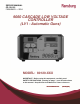
SERVICE MANUAL CP-13-02.3 FEBURARY — 2014 9060 CASCADE LOW VOLTAGE CONTROLLER (LV1 - Automatic Guns) MODEL: 80120-XXX IMPORTANT: Before using this equipment, carefully read SAFETY PRECAUTIONS, starting on page 1, and all instructions in this manual. Keep this Service Manual for future reference. Service Manual Price: $50.00 (U.S.
CP-13-02.
9060 Cascade Low Voltage Controller - Contents CONTENTS SAFETY: PAGE 1-6 SAFETY PRECAUTIONS ......................................................................................................... 1 HAZARDS / SAFEGUARDS................................................................................................... 2-5 INTRODUCTION: 7-16 GENERAL DESCRIPTION........................................................................................................ 7 SAFETY FEATURES .....................
9060 Cascade Low Voltage Controller - Contents CONTENTS PAGE OPERATION (Cont.): 29-42 LOCKOUTS ....................................................................................................................... 32-33 KV TEST JUMPER ................................................................................................................. 33 REMOTE I/O MONITORING DIAGNOSTIC MODE ........................................................... 33-35 PARAMETER ADJUSTMENT MODE ..........................
CP-13-02.
9060 Cascade Low Voltage Controller - Safety SAFETY SAFETY PRECAUTIONS Before operating, maintaining or servicing any Ransburg electrostatic coating system, read and understand all of the technical and safety literature for your Ransburg products. This manual contains information that is important for you to know and understand. This information relates to USER SAFETY and PREVENTING EQUIPMENT PROBLEMS. To help you recognize this information, we use the following symbols.
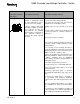
9060 Cascade Low Voltage Controller - Safety AREA HAZARD Tells where hazards Tells what the hazard is. may occur. Spray Area Fire Hazard SAFEGUARDS Tells how to avoid the hazard. Fire extinguishing equipment must be present in the spray area and tested periodically. Improper or inadequate operation and maintenance proce- Spray areas must be kept clean to prevent the dures will cause a fire hazard. accumulation of combustible residues.
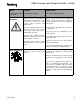
9060 Cascade Low Voltage Controller - Safety AREA HAZARD SAFEGUARDS Tells where hazards may occur. Tells what the hazard is. Tells how to avoid the hazard. Spray Area Fire and/or explosion. Electrostatic arcing MUST be prevented. The 78789 control panel, LEPS5001 power supply and all other electrical equipment must be located outside Class I or II, Division 1 or 2 hazardous areas, in accordance with NFPA-33. Test only in areas free of flammable or combustible materials.
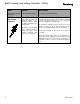
060 Cascade Low Voltage Controller - Safety AREA HAZARD Tells where hazards Tells what the hazard is. may occur. Electrical Equipment High voltage equipment is utilized. Arcing in areas of flammable or combustible materials may occur. Personnel are exposed to high voltage during operation and maintenance. SAFEGUARDS Tells how to avoid the hazard. The power supply, optional remote control cabinet, and all other electrical equipment must be located outside Class I or II, Division 1 and 2 hazardous areas.
9060 Cascade Low Voltage Controller - Safety AREA HAZARD SAFEGUARDS Tells where hazards Tells what the hazard is. Tells how to avoid the hazard. may occur. Spray Area / High Voltage Equipment There is a high voltage device that can induce an electrical charge on ungrounded objects which is capable of igniting coating materials. Parts being sprayed must be supported on conveyors or hangers and be grounded. The resistance between the part and ground must not exceed 1 megaohm.
9060 Cascade Low Voltage Controller - Safety NOTES CP-13-02.
9060 Cascade Low Voltage Controller - Introduction INTRODUCTION GENERAL DESCRIPTION The Ransburg 9060 Cascade Low Voltage Controller (80120-XXX) is used to provide high voltage for electrostatic application equipment. It uses a combination of proven high voltage generation technology and microprocessor-based control. It uses a variable voltage output to drive an external cascade that amplifies the voltage to a high kV level. It also uses current feedback information to maintain the desired set point.
9060 Cascade Low Voltage Controller - Introduction SPECIFICATIONS Environmental Operating Temperature: Storage and Shipping Temperature: 0°C to +40°C -40°C to +85°C (Allow power supply to go to room temperature before use) 95% Non-Condensing Humidity: Physical Height: 14.0 cm (5.5 inches) Width: 21.6 cm (8.5 inches) Depth: 19.1 cm (7.5 inches) 3.4 kg (7.5 lbs.) Weight: Electrical Input Voltage: 100-240 VAC 50 or 60 Hz Frequency: Current: 1 A max. RMS Wattage: 40 watts (max.
9060 Cascade Low Voltage Controller - Introduction FRONT BACK 9060 CONTROLLER FEATURES No. Description No.
9060 Cascade Low Voltage Controller - Introduction OPERATOR INTERFACE The 9060 Controller shown in Figure 3, has a simple operator interface consisting of 7 LEDs (Light Emitting Diodes), one (1) power switch, seven (7) buttons, one (1) current LED bargraph, and two (2) screens containing sevensegment displays. LOCAL Mode LED Indicator The LOCAL mode LED indicator is a left pointing triangle and is located on the left side the HV control button on the center of the operator interface.
9060 Cascade Low Voltage Controller - Introduction pressed with the reset button, at the same time, the screen will display the resettable High Voltage ON operating hours for 3 seconds on the display screens. Preset 2 Button The Preset 2 Button (in the center below the kV display) is used by itself to select “Voltage Preset 2” in the LOCAL operating mode.
9060 Cascade Low Voltage Controller - Introduction Interlock I/O Connector The interlock I/O connector is located just to the right of the AC inlet receptacle. This connector is provided as the entry point for interlock signal wiring for the booth fan, conveyor, and solvent supply. The connector includes the required cable grommet hardware to keep wiring in place with minimal strain. For more information on the interlock connections, please see the “Installation” section of the service manual.
9060 Cascade Low Voltage Controller - Introduction SIGNAL INTERFACE LOCAL MODE relay signal is activated when a Fault Condition or Overload Condition has faulted the 9060 Controller. The 9060 Controller LOCAL mode is normally used for handguns, or very simple automatic gun systems. Handguns require only one signal input for operation, the trigger signal.
9060 Cascade Low Voltage Controller - Introduction NOTE Sinking and Sourcing refers to the signal that is applied to activate an input. If you are applying a +24 VDC signal to the input to activate it, you are sourcing. If you are applying a GROUND signal to the input, you are sinking. or all sinking inputs. For information regarding configuring the inputs, refer to the “Installation” section of this manual. preset buttons on the left side of the front panel.
9060 Cascade Low Voltage Controller - Introduction Remote Mode Configuration is set to enable Analog Control. For more information on how to configure Remote Mode, please see the Operation section of this service manual. ! WARNING DO NOT attempt to use both analog voltage and analog current at the same time. The analog inputs are mutually exclusive. Using both inputs simultaneously will damage the input circuit.
9060 Cascade Low Voltage Controller - Introduction High Voltage On (Relay Output, Dry Contact) NOTES The “HV on” signal (TB2-3) is available in both LOCAL and REMOTE modes. This signal, being a relay controlled signal, can be configured as either an AC or DC signal using the Relay Common Input as the signal source. For information regarding the relay contact voltage ratings, please refer to the “Relay Output Contacts” portion of the “Installation” section of the manual.
9060 Cascade Low Voltage Controller - Installation INSTALLATION GENERAL INFORMATION LOCATION OF THE 9060 The following section contains general information on the installation of both local and remote systems using the 9060 Cascade Low Voltage Controller. Install the Controller in an area outside the hazardous location in accordance with federal, state, and local codes.
9060 Cascade Low Voltage Controller - Installation ELECTRICAL NOISE Electrical noise refers to stray electrical signals in the atmosphere at various signal strengths and frequencies that can affect the operation of equipment. One of the best ways to prevent this is to shield the equipment and cables within a continuous ground envelope, such that any incident noise will be conducted to earth ground before it can affect the circuit conductors.
9060 Cascade Low Voltage Controller - Installation affected by electrical noise when the above methods are utilized. I/O CONNECTIONS For maximum noise immunity, I/O wiring should be run in conduit or cables having a foil shield with an overall braided shield. The foil shield provides 100% shielding, while the braid provides a means of making proper 360° shield terminations at the cable to cabinet connection points.
9060 Cascade Low Voltage Controller - Installation NOTE TB1 In general, conduit must be used for approved AC installation, however, if national and local codes permit, the AC power may be supplied via the factory supplied line cord. If conduit is utilized, the Controller AC input wiring may be routed through an optional explosion proof switch mounted on or near the spray booth where it will be convenient to the operator.
9060 Cascade Low Voltage Controller - Installation SAFETY GROUND ! Failure to connect interlocks could re- Crimp the appropriate connector onto the ground wire assembly and install from the Controller ground stud, located on the side panel, to a true earth ground. ! sult in a fire or explosion. ! OFF before flushing the spray applicator with solvent. NEVER flush the spray applicator with high voltage ON, as this is a severe fire hazard and risk to personnel safety.
9060 Cascade Low Voltage Controller - Installation Figure 11: Controller Schematic CP-13-02.
9060 Cascade Low Voltage Controller - Installation of 300V and 105°C and its conductors should be 0.8mm2 (18 AWG) minimum. Secure the cable to the interlock connector as described in “I/O Connections” in the “Installation” section of this manual so that the shield of the cable is connected to the chassis of the enclosure. 5. Replace the top cover, secure the screws, replace the fuses, and reconnect the AC source.
9060 Cascade Low Voltage Controller - Installation RELAY CONTACT OUTPUTS LOCAL MODE (TRIGGER SIGNAL ONLY) A set of relay contacts for high voltage (CR1) and fault (CR2) conditions is provided at TB2-3 and TB2-1 (See Figure 8). One end of these relay contacts are connected together and also connected to a source input terminal TB2-2 (See Figure 11).
9060 Cascade Low Voltage Controller - Installation ! WARNING Trigger Signal Position 5 In TB4 The 9060 Cascade Low Voltage Con- troller is designed to handle both a sinking or sourcing trigger input. DO NOT use a sourcing (User Supplied 24VDC) trigger signal with the 9060 jumpers set for sinking (User Supplied Ground) inputs or vice versa. Sourcing and sinking inputs have different current flow paths.
9060 Cascade Low Voltage Controller - Installation Jumper 2 Jumper 1 Figure 15: Local/Remote Board Jumper Headers The Relay Contact Outputs are normally included as output signal indicators for a control system and are wired using a few of the conductors in the I/O cable. For more information about the Relay Contact Outputs wiring, please refer to the prior “Installation” section on that topic.
9060 Cascade Low Voltage Controller - Installation 3. Route the selected shielded cable through the standard I/O connector and secure it to the connector as described in “I/O Connections” in the “Installation” section of this manual so that the shield of the cable is connected to the chassis of the enclosure. Ensure that enough wire length is available to allow for proper wiring of all of the I/O signals. 4. Connect the conductors to the respective remote I/O signal locations.
9060 Cascade Low Voltage Controller - Installation 6. The local/remote board (Assy# A13123), jumpers must be adjusted into one of the two REMOTE settings, based on the desired input type, to allow for REMOTE mode operation. The location of the jumpers on the board is displayed in Figure 15. Use the REMOTE mode jumper settings table for the jumper settings based upon your specific input. REMOTE Mode Jumper Settings Remote Source Remote Sink JMP1 3-4 3-4 JMP1 5-7 5-7 JMP2 2-3 1-2 Jumper 8.
9060 Cascade Low Voltage Controller - Operation OPERATION START-UP ! After all installation procedures are completed, operation of the applicator may begin. When the ON-OFF switch is turned on, the kV display will show the applicator type the 9060 Controller is configured for and the µA (microamp) display will show the current software revision level as shown in Figure 18. These items are displayed for approximately 5 seconds. Gun Type Number Software Rev.
9060 Cascade Low Voltage Controller - Operation Triggering High voltage is actuated by the presence of an active trigger signal. In LOCAL mode, this is normally accomplished by pulling the trigger of the handgun to start the flow of atomizing and fan control air through the applicator. When the applicator is triggered, an an air flow switch (optional) is activated, and the trigger signal is issued to the 9060 unit. In REMOTE mode, the control system logic issues the trigger signal to the 9060 unit directly.
9060 Cascade Low Voltage Controller - Operation DI/DT CONFIGURATION (For 80100-51X Units Only) The 9060 Voltage Controller, model 80100-51X, for use with the ATEX approved Aerobell 168 applicator, contains a di/dt (rate of change in current with respect to time) safety overload fault and is used in addition to the standard current overload fault. This is an adjustable setting which determines the maximum current increase that can occur during a specific time period.
9060 Cascade Low Voltage Controller - Operation LOCKOUTS There are lockouts that may be done at the PC board (see Figure 22). These lockouts may be used individually or in combination as required. If the jumpers are disconnected, the original functions are re-enabled. After changing any jumpers, the AC power must cycled for the new setting to take affect. Figure 23: Jumper Location - Front Panel Lockout NOTE Some lockouts are sealed using sealant to prevent them from being modified for safety reasons.
9060 Cascade Low Voltage Controller - Operation NOTE Some applicators, ES (Evolver SE, EstaQuick) and Ab (Aerobell 168), have adjustable overload values. Please refer to the “Parameter Adjustment Menu” part of the “Operations” section for information on adjusting the overload value. KV TEST JUMPER To assist in testing and troubleshooting, a jumper (J8) has been added to the main PC board. By covering (shorting) both terminals of this jumper, the high voltage of the spray applicator can be activated.
9060 Cascade Low Voltage Controller - Operation Analog Signal Monitoring Mode In the analog signal monitoring mode the kV display will show an “A#” with the “#” being the analog signal index as shown in Figure 26. The analog-to-digital converted (ADC) value of the currently selected analog signal is displayed on the µA display. The displayed value can be in the range of 0 to 1023, with 0 corresponding to the minimum analog input value.
9060 Cascade Low Voltage Controller - Operation To navigate through the digital indexes, use the - and + buttons. Both buttons change the index by 1 for each press and will automatically wrap back around when the either end of the list is reached. Gun Type/Firmware Version Mode This sub mode will display the gun type display value on the kV display and the firmware version number on the µA display as shown during startup in Figure 18 during startup.
9060 Cascade Low Voltage Controller - Operation ! CAUTION Be careful when using the parameter adjustment mode, if you select something and are unsure if you’ve changed it, deselect it using Preset 2. Modifying a Parameter After a parameter has been selected using the preset 2 button and is flashing, the + and - keys can be used to increase or decrease the value of the parameter. Each parameter has its own incremental values and limits listed in the Adjustable Parameters Table.
9060 Cascade Low Voltage Controller - Operation Single Pushes Increment Voltage Down (-) or Up (+)in Single Increments. Holding Button Increments Voltage Down (-) or Up (+) in Increments of 5 Kv. REMOTE MODE ONLY OPERATIONS Remote Mode Control Behavior Set Point Select Button Figure 31: kV Adjust/Setpoint Buttons Adjusting Presets To adjust one of the preset setpoints, ensure the applicator is off in LOCAL mode and select the desired setpoint by pressing the corresponding setpoint button.
9060 Cascade Low Voltage Controller - Operation Tripleset Selection Setpoint 1 Setpoint 0 Figure 33: Remote Mode Configuration Menu 4. The display indicates the status of the Analog Control (AC) mode on the uA display on the right side of the front panel. When Tripleset Selection is configured, OFF is displayed. If Analog I/O control is selected, “-ON” is displayed. 5. To change the Analog Control setting: Press (1) to turn ON the Analog Control Press (3) to turn OFF the Analog Control 6.
9060 Cascade Low Voltage Controller - Operation The analog input signals are calibrated during manufacturing. The following table lists the analog input voltages corresponding to their respective setpoints from 20kV to 90kV in 10kV increments. The actual analog value can vary slightly from unit to unit, but should be no more than ±0.1V off the value listed below. Analog Input Voltages Setpoint Analog Voltage 20kV 2.0V 30kV 3.0V 40kV 4.0V 50kV 5.0V 60kV 6.0V 70kV 7.0V 80kV 8.0V 90kV 9.
9060 Cascade Low Voltage Controller - Operation TRIGGER SIGNAL TIMING: The trigger signal minimum hold time is 10 ms. ! CAUTION The signal Hold Times are the minimum required for the processor to detect the signal. During actual operations, signal time durations are expected to be much greater than the minimums. FAULT DESCRIPTIONS For in depth troubleshooting information on the 9060, please refer to the “Fault Troubleshooting” portion of the Maintenance Section of this service manual.
9060 Cascade Low Voltage Controller - Operation Current Limit Fault (CL) This fault occurs if the output current exceeds the maximum current by 20µA. This fault can be caused by excessive overspray on the applicator or a paint formulation that is too conductive. It may also be caused by a bad pc board. Clean the applicator, check the paint formulation, and re-test. If still a problem, replace the pc board. See Fault Troubleshooting Section for more information.
9060 Cascade Low Voltage Controller - Operation Over Voltage Fault (OU) DI/DT Overload Fault (dOL) This fault will occur if the microprocessor detects the unit is trying to output voltage above the required for the specific applicator type. If this occurs, reset the Controller. If this fault continues to occur, replace the main PC board. This fault is ONLY applicable to 80100-51X units.
9060 Cascade Low Voltage Controller - Maintenance MAINTENANCE TROUBLESHOOTING GUIDE General Problem Possible Cause Solution Blank Display 1. No power 1. Check the power connections and verify they are fully connected and power is available. Power cycle the unit off and back on. 2. Blown fuse 3. Faulty +24 volt power supply 2. Check Fuses and replace if blown using the replacement fuses inside the lid of the unit. 3. Check green led on 24 volt power supply when power is applied LED must be on.
9060 Cascade Low Voltage Controller - Maintenance Fault Description Solution Ground Fault (GF) The Ground Fault is typically caused by a ground connection problem, and can create a safety hazard. It can occur without high voltage and will not reset. 1. Check for secure connection on both ends of the low voltage cable and tighten if necessary. Re-test for GF fault. 2. Replace low voltage cable. 3. Replace external cascade or send in for repair.
9060 Cascade Low Voltage Controller - Maintenance Fault Description Solution Voltage Cable Fault (UC) The Voltage Feedback Fault indicates the cascade drive signal is not present. It typically occurs when high voltage is triggered. 1. Turn off the voltage controller and remove the high voltage cable from external cascade assembly. 2. Turn on the power, wait for 0uA display, and place HV test jumper J8 in shorted position. If the UC fault occurs, send the high voltage controller in for repair.
9060 Cascade Low Voltage Controller - Maintenance NOTES CP-13-02.
9060 Cascade Low Voltage Controller - Parts Identification PARTS IDENTIFICATION 9060 CASCASDE LOW VOLTAGE CONTROLLER MODEL IDENTIFICATION * When ordering, use 80120-A1B as indicated by Table A and B. Three digits must follow the basic part number, for example: 80120 - A 1 B Basic Part Number Plug Selection (TABLE B) Model Selection (TABLE A) * Model number and serial number of the voltage controller is located on the left outside face of the main enclosure. Table A - Model Selection Dash No.
9060 Cascade Low Voltage Controller - Parts Identification 9060 Cascade Low Voltage Controller - Parts List Part # Description 72771-06 Fuse (250V, 1A, 5mm x 20mm) 80116-41 9060 Cascade Low Voltage Controller PC Mainboard (80120-31X, 41X) 80116-68 9060 Cascade Low Voltage Controller PC Mainboard (80120-51X) 80124-00 9060 Cascade Low Voltage Controller Local/Remote Board (A13123) 79428-00 Power Supply, 24V (24VDC Power Supply 1PS) 76434-01 Switch, Rocker (On-Off Switch) Figure 43: Part Identif
9060 Cascade Low Voltage Controller - Accessories ACCESSORIES 9060 Low Voltage Controller - Accessories List 49 Part # Description 76652-01 HV Probe 76652-02 Meter w/Test Leads 76652-03 Paint Test Probe w/Meter 76652-04 Deluxe Kit (Include HV Probe, Meter w/Test Leads, and Paint Test Probe) 76453-00 Conduit Adapter Kit CP-13-02.
9060 Cascade Low Voltage Controller - Warranty Policies WARRANTY POLICIES LIMITED WARRANTY Ransburg will replace or repair without charge any part and/or equipment that falls within the specified time (see below) because of faulty workmanship or material, provided that the equipment has been used and maintained in accordance with Ransburg's written safety and operating instructions, and has been used under normal operating conditions. Normal wear items are excluded.
9060 Cascade Low Voltage Controller - Wiring Configurations WIRING CONFIGURATIONS Remote Analog Voltage Control (Sourcing Configuration) The following example configuration uses the following: • Sourcing Configured Digital Inputs (Apply 24VDC to activate the input) • Permanently Wired into Remote Mode (Jumper Wire from TB3-6 to TB4-4) • Normally Open (NO) Contact to Activate Reset when unit is Faulted • Normally Open (NO) Contact to Activate HV Trigger to turn on HV Cascade • 0-10V Analog Voltage
9060 Cascade Low Voltage Controller - Wiring Configurations Remote Analog Current Control (Sourcing Configuration) The following example configuration uses the following: • Sourcing Configured Digital Inputs (Apply 24VDC to activate the input) • Permanently Wired into Remote Mode (Jumper Wire from TB3-6 to TB4-4) • Normally Open (NO) Contact to Activate Reset when unit is Faulted • Normally Open (NO) Contact to Activate HV Trigger to turn on HV Cascade • 0-20mA Analog Current Control Signal Figure
9060 Cascade Low Voltage Controller - Wiring Configurations Remote Tripleset Point Control (Sourcing Configuration) The following example configuration uses the following: • Sourcing Configured Digital Inputs (Apply 24VDC to activate the input) • Normally Open (NO) Contact to Activate Reset when unit is Faulted • Normally Open (NO) Contact to Activate HV Trigger to turn on HV Cascade • Normally Open (NO) Contact to Activate remote mode.
9060 Cascade Low Voltage Controller - Wiring Configurations Remote Analog Voltage Control (Sinking Configuration) The following example configuration uses the following: • Sinking Configured Digital Inputs (Apply GND to activate the input) • Permanently Wired into Remote Mode (Jumper Wire from TB4-6 to TB4-4) • Normally Open (NO) Contact to Activate Reset when unit is Faulted • Normally Open (NO) Contact to Activate HV Trigger to turn on HV Cascade • 0-10V Analog Voltage Control Signal Figure 47:
9060 Cascade Low Voltage Controller Manufacturing 1910 North Wayne Street Angola, Indiana 46703-9100 Telephone: 260-665-8800 Fax: 260-665-8516 Technical Service—Assistance 320 Philips Ave. Toledo, Ohio 43612-1493 Telephone (toll free): 800-233-3366 Fax: 419-470-2233 Technical Support Representative will direct you to the appropriate telephone number for ordering Spare Parts. © 2013 Ransburg. All rights reserved. Models and specifications subject to change without notice. Form No. CP-13-02.3 Litho in U.