
User Manual


CP-97-04.3
2525
2525
25
9040 Cascade Low Voltage Control Unit - Maintenance
> In the control unit, ground is passed
from the ground stud to the chassis via
the front panel screws. Ensure the front
panel screws are securely fastened and
repeat step 3 before searching for faulty
internal connections.
NOTENOTE
NOTENOTE
NOTE
MAINTENANCEMAINTENANCE
MAINTENANCEMAINTENANCE
MAINTENANCE
ROUTINE PREVENTIVEROUTINE PREVENTIVE
ROUTINE PREVENTIVEROUTINE PREVENTIVE
ROUTINE PREVENTIVE
MAINTENANCEMAINTENANCE
MAINTENANCEMAINTENANCE
MAINTENANCE
In general, little maintenance is necessary to
ensure proper operation. It is important, however,
to keep the interior of the unit clean and free from
moisture or foreign material. For this reason:
• Keep the exterior of the unit free from dust
accumulation.
• Always clean the exterior prior to accessing the
interior.
• Access the interior only to perform mainte-
nance or repair
.
TROUBLESHOOTINGTROUBLESHOOTING
TROUBLESHOOTINGTROUBLESHOOTING
TROUBLESHOOTING
Ground TGround T
Ground TGround T
Ground T
est Procedureest Procedure
est Procedureest Procedure
est Procedure
Equipment Required: Ohmmeter - toEquipment Required: Ohmmeter - to
Equipment Required: Ohmmeter - toEquipment Required: Ohmmeter - to
Equipment Required: Ohmmeter - to
measure resistancemeasure resistance
measure resistancemeasure resistance
measure resistance
If shocks or sparks are noticed at any point in the
spray system, immediately turn off the control unit
and check the complete system for proper
grounding. Proper grounding of the applicator
system can be verified as follows:
1. Ensure that the clamp of the Ground Wire
Assembly is connected to true earth ground. The
resistance between the clamp and a known earth
ground should read less than 25 ohms.
2. Place one end of the ohmmeter on the clamp
of the ground wire assembly and the other end on
the control unit ground stud. If the ohmmeter reads
greater than 25 ohms replace the Ground Wire
Assembly.
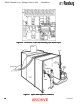
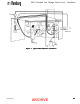
3. Disconnect the low voltage applicable cable and
connect one lead of the ohmmeter to the ground
stud and the other to the center pin of the low
voltage cable socket on the control unit. If the
ohmmeter reads greater than 25 ohms, repair the
internal connections between these points (green
wires from 1TB-GROUND TO 1GND (see Figure
10) and from 1TB-GROUND to center pin of low
voltage cable socket).
4. Connect one end of the ohmmeter to the center
pin of the low voltage cable connector on the cable,
and the other to the metal applicator body
(automatics) or handle bracket (applicators). If
the ohmmeter reads greater than 25 ohms replace
the low voltage cable.
> On applicators, ground is passd from
the low voltage cable to the handle via the
handle set screw. Ensure the set screw
is completely tightened and repeat step 4
before replacing the low voltage cable on
applicator units.
NOTENOTE
NOTENOTE
NOTE
ARCHIVE