SERVICE MANUAL CP-97-04.3 (Replaces CP-97-04.
N O T E : This manual has been changed from CP-97-04.2 to revision CP-97-04.3. Reasons for this change are noted under “Manual Change Summary” inside the back cover of this manual. ARCHIVE CP-97-04.
9040 Cascade Low Voltage Control Unit - Contents CONTENTS PAGE 1-4 SAFETY: SAFETY PRECAUTIONS........................................................................................................... 1 HAZARDS/SAFEGUARDS......................................................................................................... 2-4 ATEX 5-6 EUROPEAN ATEX DIRECTIVE................................................................................................. 5 EUROPEAN ATEX LABELS.......................
9040 Cascade Low Voltage Control Unit - Safety SAFETY SAFETY PRECAUTIONS Before operating, maintaining or servicing any ITW Ransburg electrostatic coating system, read and understand all of the technical and safety literature for your ITW Ransburg products. This manual contains information that is important for you to know and understand. This information relates to USER SAFETY and PREVENTING EQUIPMENT PROBLEMS. To help you recognize this information, we use the following symbols.
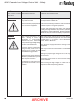
9040 Cascade Low Voltage Control Unit - Safety AREA HAZARD SAFEGUARDS Tells where hazards Tells what the hazard is. Tells how to avoid the hazard. may occur. Spray Area Fire extinguishing equipment must be present in the spray area and tested periodically. Fire Hazard Improper or inadequate operation and maintenance procedures will Spray areas must be kept clean to prevent the accumulation of combustible residues. cause a fire hazard.
9040 Cascade Low Voltage Control Unit - Safety AREA HAZARD SAFEGUARDS Tells where hazards Tells what the hazard is. Tells how to avoid the hazard. may occur. General Use and Maintenance Improper operation or maintenance Personnel must be given training in accordance with may create a hazard. the requirements of NFPA-33. Personnel must be properly trained Instructions and safety precautions must be read and in the use of this equipment. understood prior to using this equipment.
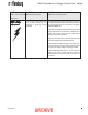
9040 Cascade Low Voltage Control Unit - Safety AREA HAZARD SAFEGUARDS Tells where hazards Tells what the hazard is. Tells how to avoid the hazard. may occur. Spray Area / High Voltage Equipment This is a high voltage device that can produce electrical arcs capable of igniting coating materials. Parts being sprayed must be supported on conveyors or hangers and be grounded. The resistance between the part and ground must not exceed 1 megohm. (Reference NFPA-33.
9040 Cascade Low Voltage Control Unit - Atex EUROPEAN A TEX DIRECTIVE 94/9/EC, ANNEX II, 1.0.6 ATEX The following instructions apply to equipment covered by certificate number Sira 08ATEX5040X: 1. The equipment may be used with flammable gases and vapors with apparatus groups II and with temperature class T6. 2. The equipment is only certified for use in ambient temperatures in the range +12.8°C to +40°C and should not be used outside this range. 3.
040 Cascade Low Voltage Control Unit - Atex 9040 Cascade Low V oltage Voltage Control Unit A TEX Product ATEX Marking Definitions Label 72562 Ex Certificate Number: Sira 08ATEX5040X Sira = Notified Body performing EC-type examination 08 = Year of certification ATEX = Reference to ATEX Directive 5 = Protection Concept Code (code 5 is titled Encapsulation) 040 = Document serial number X = Special conditions for safe use apply Label 79318 Product Marking II 2 G Ex = Specific marking of explosive protect
9040 Cascade Low Voltage Control Unit - Introduction INTRODUCTION DESCRIPTION The ITW Ransburg REA Process The REA Process is an air atomized method for applying coatings to objects electrostatically. The REA system applies a high voltage DC charge to the applicator nozzle electrode, creating an electrostatic field between the atomizer and the target object. The target is electrically grounded through its support that may be either stationary or moving.
9040 Cascade Low Voltage Control Unit - Introduction required to operate the spray applicator in one convenient location. See “Parts Identification” section of this manual for information on ordering Totalizer or Pneumatics modules. The 9040 Cascade control unit has also been modularly designed so that two half rack 9040 chassis will fit into one full rack enclosure, in multiple applicator installations. The full rack enclosure has been designed for mounting in standard 19-inch rack mount cabinets.
9040 Cascade Low Voltage Control Unit - Introduction The 9040 Cascade control unit is available from the factory in the following versions only: SPECIFICA TIONS SPECIFICATIONS 1. One control unit with no Totalizer or Pneumatics modules Environmental / Physical Height: 5.2-Inches 2. One control unit with one Totalizer module and no Pneumatics module Width: 16.9-Inches (19-Inches ear to ear) 3. One control unit with one Totalizer module and one Pneumatics module Depth: 12.1-Inches Weight: 15 lbs.
9040 Cascade Low Voltage Control Unit - Introduction FRONT VIEW BACK VIEW * Air Flow Switch used in -1XXXX, -6XXXX, and -7XXXX. Two pressure switches used in -3XXXX, -4XXXX, -5XXXX, -8XXXX, and -9XXXX. No pressure switch or flow switch used in -2XXXX. Figure 1: 9040 Cascade Control Unit Features CP-97-04.
9040 Cascade Low Voltage Control Unit - Installation INST ALLA TION INSTALLA ALLATION ! WARNING ! > The 9040 Cascade control unit MUST be located outside the hazardous area. (See NFPA-33, OSHA, and ITW Ransburg Literature “Operating Your Electrostatic Coating System Safely”.) > The user MUST read and be familiar with the SAFETY and SAFETY PRECAUTIONS.
9040 Cascade Low Voltage Control Unit - Installation For installations where it is required to run the AC input wiring in conduit, perform the following: 1. Ensure the AC line cord is unplugged and remove the AC Inlet Receptacle wiring from 1TBL1, 1TB-N and 1TB-Ground (see Figure 2 for AC input wiring locations).
9040 Cascade Low Voltage Control Unit - Installation NOTE ! > 9040 units shipped from the factory for 115 VAC input will have a 72771-06, 1 amp front panel fuse installed. While 9040 units shipped from the factory for 230 VAC input will have a 72771-01, 0.5 amp front panel fuse installed. If the other input is required, it is recommended that the fuse be changed in order to keep the same level of protection. Both fuses are shipped with 9040 control units.
9040 Cascade Low Voltage Control Unit - Installation As outlined in NFPA-33 and OSHA, the AC power line must be series interlocked with both the exhaust fan and conveyor. To interlock the 9040 Cascade control unit with the exhaust fan and conveyor perform the following: 1. Ensure the front panel fuse is removed, the control unit is unplugged, and the ON/OFF switch is in the OFF positon. 2. Loosen the front panel screws and slide the control unit chassis out.
9040 Cascade Low Voltage Control Unit - Installation External High V oltage Control Voltage External Overload Reset If a method of high voltage triggering, other than the factory supplied method, is required, the 9040 Cascade control unit allows for external high voltage control from a PLC, pressure switch, airflow switch, or other user-supplied device. To turn the high voltage on, the user-supplied device must create a contact closure between terminals 1 and 2 of the External Wiring Plug (2PL).
9040 Cascade Low Voltage Control Unit - Installation Analog Current Output Signal An analog current output signal is available from the 9040 control unit at 2PL-8 (outside) or 2SOC8 (inside). This signal can be connected to a recording device (strip chart recorder, data acquisition unit, etc.) to monitor the output current of the control unit over time. This signal should be referenced to earth ground. The input resistance of the recording device should be 5 megohms or greater.
9040 Cascade Low Voltage Control Unit - Installation To utilize the T riple Setpoint Feature perform Triple the following (refer to Figures 5a and 5b): 1. Ensure the front panel fuse is removed, the control unit is unplugged, and the ON/OFF switch is in the OFF position. High voltage outputs selected by TB1-1 (Setpoint 1) and TB1-3 (Setpoint 2) can be adjusted by tweaking potentiometers P1 and P2 on the Triple Setpoint Board, respectively.
9040 Cascade Low Voltage Control Unit - Installation ! CAUTION ! CAUTION > DO NOT operate the Analog Input Feature with the jumpers removed from JP2 or JP3, or with the jumpers in any other positions that those shown on the PC board silkscreen. > DO NOT use the analog input board as a method for turning high voltage ON and OFF. The control unit has specific inputs for this purpose (see “Pneumatic Connections and External High Voltage Control” in this section). 5.
9040 Cascade Low Voltage Control Unit - Installation Figure 5b: Combination Triple Setpoint/Analog Input Board Layout Figure 6: T ypical REA Applicator Installation Typical 19 ARCHIVE CP-97-04.
9040 Cascade Low Voltage Control Unit - Installation Figure 7: T ypical REM Applicator Installation Typical CP-97-04.
9040 Cascade Low Voltage Control Unit - Operation OPERA TION OPERATION ! WARNING ! WARNING > The user MUST read and be familiar with the SAFETY PRECAUTIONS and SAFETY SECTIONS of this manual and the ITW Ransburg safety literure therein identified BEFORE OPERATING the 9040 Cascade control unit. > The electrical discharge that is available from the charging electrode of the applicator must not exceed 0.25 mJ of energy.
9040 Cascade Low Voltage Control Unit - Operation OPERA TING OPERATING PROCEDURES High V oltage Adjustment Knob Voltage 1. Ensure that the AC power, pneumatic and low voltage cables are connected as described in the “Installation” section of this manual. Overload Indicator/Reset Button ! The high voltage adjustment knob allows infinite control of the applicator electrode voltage between 0 and rated kV. CAUTION Check that the control unit is > properly grounded! 2.
9040 Cascade Low Voltage Control Unit - Operation Automatic applicators, however, typically have a fixed distance between electrode and target and thus it is not likely that the spray applicator would come into close proximity with the part during normal use. If it should, then it is desired that an overload occur to alert maintenance so that the condition may be corrected.
9040 Cascade Low Voltage Control Unit - Operation NOTES CP-97-04.
9040 Cascade Low Voltage Control Unit - Maintenance MAINTENANCE ROUTINE PREVENTIVE MAINTENANCE In general, little maintenance is necessary to ensure proper operation. It is important, however, to keep the interior of the unit clean and free from moisture or foreign material. For this reason: 3. Disconnect the low voltage applicable cable and connect one lead of the ohmmeter to the ground stud and the other to the center pin of the low voltage cable socket on the control unit.
9040 Cascade Low Voltage Control Unit - Maintenance Control Unit Output T est Test PC Board T est Jumper Test When a lack of high voltage at the applicator indicates a problem, perform a Control Unit Output Test on the control unit to determine whether it is at fault. To assist in testing and troubleshooting, a jumper (JP4) has been incorporated on the 9040 PC board. By covering (shorting) both terminals the high voltage on relay is triggered.
9040 Cascade Low Voltage Control Unit - Maintenance The DC input to the oscillator is interlocked with 2PL terminals 1 and 2, such that the oscillator will not function unless terminals 1 and 2 of 2PL are connected together. In this manner, high voltage to the applicator is controlled as follows: 1. When air flows through the flow switch, the switch contacts close connecting 2PL-1 and 2 together, thereby providing voltage to the REA70 and REA-90 applicators. 2.
9040 Cascade Low Voltage Control Unit - Maintenance NOTES CP-97-04.
9040 Cascade Low Voltage Control Unit - Maintenance TROUBLESHOOTING FLOW CHARTS ON / OFF Switch ON ON / OFF Indicator (green LED) does not light 29 ARCHIVE CP-97-04.
9040 Cascade Low Voltage Control Unit - Maintenance TROUBLESHOOTING FLOW CHARTS (Cont.) Figure 9: Troubleshooting Diagram CP-97-04.
9040 Cascade Low Voltage Control Unit - Maintenance Figure 10: 9040 Cascade Control Unit Block Diagram 31 ARCHIVE CP-97-04.
9040 Cascade Low Voltage Control Unit - Maintenance ! WARNING > Always turn power to the control unit OFF, unplug the electrical cord from its outlet, remove the front panel fuse, and lock the control unit out before making repairs or replacements. 3. Remove fuse from fuse holder and replace with new fuse (see “Parts Identification” section of this manual for fuse part number). 4.
9040 Cascade Low Voltage Control Unit - Maintenance NOTE ! WARNING > It is recommended that the four (4) ON/ OFF switch wires be tagged with their respective terminal connections to 1SW before removing. 3. Press panel retaining clips on top and bottom of switch 1SW together and push switch out of panel from the inside. 4. Press new switch (see “Parts Identification” section of this manual to order) into panel opening with terminals 1A and 2A to the bottom of the cabinet. 5.
9040 Cascade Low Voltage Control Unit - Maintenance 7. With flow switch terminals pointing towards the main PC board, install new flow switch through chassis mounting holes. 8. Secure flow switch to side panel with two (2) hex nuts. 9. Slide chassis in, secure front panel screws, and plug control unit back in. 10. Reconnect air lines to flow switch. Pressure Switch (76580-4XXXX, -5XXXX, -8XXXX, and -9XXXX) 1. Disconnect pressure signal input line from pressure switch. LED Display Board 1.
9040 Cascade Low Voltage Control Unit - Maintenance HV Adjust Potentiometer PC Board 1. Remove knob from HV adjust potentiometer by using a 1/16” Allen wrench to remove the two (2) set screws. 1. Ensure control unit is unplugged from AC outlet, loosen front panel screws, and slide control unit chassis out. 2. Ensure control unit is unplugged from AC outlet, loosen front panel screws, and slide control unit chassis out. 2. Disconnect plugs 6PL, 7PL, and 9PL (see Figure 4). 3.
9040 Cascade Low Voltage Control Unit - Maintenance NOTES CP-97-04.
9040 Cascade Low Voltage Control Unit - Parts Identification PAR TS ARTS IDENTIFICA TION IDENTIFICATION Figure 1 1: 9040 Cascade Low V oltage Control Unit Parts Diagram 11: Voltage 37 ARCHIVE CP-97-04.
9040 Cascade Low Voltage Control Unit - Parts Identification VOLT PAR ARTS 9040 CASCADE LOW VOL TAGE CONTROL UNIT - P AR TS LIST 11) (Figure 1 1) Item # Part # 1 76892-01 76892-02 76892-04 76892-05 76892-06 76892-07 2 3 4 5 6 7 8 9 10 11 12 13 14 15 16 76892-08 76892-09 76892-16 76892-17 76434-01 70556-03 76436-91 76436-92 72231-00 13742-01 13028-01 8012-00 6039-00 25766-106 75337-05 LSME082-04 72771-06 72771-01 76449-00 70539-00 76455-01 76442-01 76441-00 76443-01 5627-00 76031-05 76031-06 76031-07
9040 Cascade Low Voltage Control Unit - Parts Identification VOLT 9040 CASCADE LOW VOL TAGE CONTROL UNIT ARTS 11) PAR TS LIST (Figure 1 1) (Cont.) Item # Part # 17 76612-01 76612-02 76612-03 76612-04 18 19 20 39 76613-11 76613-21 76613-12 76613-22 LTST5000 77653-00 Description Totalizer Fluid Monitoring Module (all parts required to add Totalizer system to existing 9040 Rack): Intrinsically Safe U.S.
9040 Cascade Low Voltage Control Unit - Parts Identification Recommended Spare Parts for 9040 Cascade Control Unit for REA70, REA90, and REM Applicators (Models 76580-1XXXX, -2XXXX, -6XXXX, -7XXXX) Description Part Number No.
9040 Cascade Low Voltage Control Unit - Warranty Policies WARRANTY POLICIES LIMITED W ARRANTY WARRANTY ITW Ransburg will replace or repair without charge any part and/or equipment that falls within the specified time (see below) because of faulty workmanship or material, provided that the equipment has been used and maintained in accordance with ITW Ransburg's written safety and operating instructions, and has been used under normal operating conditions. Normal wear items are excluded.
MANUAL CHANGE SUMMAR Y SUMMARY This manual was published to replace Service Manual CP-97-04.2 to make the following changes: 1. Added “ “ to the “Front Cover”. 2. Added “Atex” section and “Labels 42562 and 79318” to the “Atex” section. CP-97-04.
Service Manual Price: €25.00 25.00 (Euro) $30.00 (U.S.) Manufacturing 1910 North Wayne Street Angola, Indiana 46703-9100 Telephone: 260/665-8800 Fax: 260/665-8516 Technical/Service Assistance Automotive Assembly and Tier I Industrial Systems Ransburg Guns www.itwransburg.