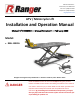
645 Lemonwood Dr. Santa Paula, CA 93060 USA Toll Free: 1 (800) 253-2363 Telephone: 1 (805) 933-9970 rangerproducts.com ATV / Motorcycle Lift Installation and Operation Manual Manual P/N 5900183 — Manual Revision E — February 2020 Model: • RML-1500XL Designed and engineered by BendPak Inc. in Southern California, USA. Made in China. ⚠ DANGER Read the entire contents of this manual before using this product.
Manual. RML-1500XL ATV/Motorcycle Lift, Installation and Operation Manual, Manual P/N 5900183, Manual Revision E, released February 2020. Copyright. Copyright © 2020 by BendPak Inc. All rights reserved. You may make copies of this document if you agree that: you will give full attribution to BendPak Inc., you will not make changes to the content, you do not gain any rights to this content, and you will not use the copies for commercial purposes. Trademarks.
Table of Contents Introduction 3 Operation 18 Shipping Information 4 Maintenance 22 Safety Considerations 4 Troubleshooting 23 Components 6 Labels 24 FAQ 8 Parts Drawings 25 Specifications 9 Maintenance Log 27 Installation 10 Introduction This manual describes the RML-1500XL ATV/Motorcycle Lift from BendPak Ranger, which lets you raise a Motorcycle or ATV of up to 1,500 pounds / 680 kg high off the ground.
Shipping Information Your equipment was carefully checked before shipping. Nevertheless, you should thoroughly inspect the shipment before you sign to acknowledge that you received it. When you sign the bill of lading, it tells the carrier that the items on the invoice were received in good condition. Do not sign the bill of lading until after you have inspected the shipment.
• • • • • • • • Do not make any modifications to the product. The Air/Hydraulic Pump is a tripping hazard if you keep it on the ground. Make sure everyone who uses the Lift or works near it is aware of the location of the Pump. Before lowering the Lift, check underneath to make sure there are no people or equipment under it. There must not be anything under it that would interfere with normal use. Use the product indoors on a flat, concrete floor.
Components The main components of the RML-1500XL ATV/Motorcycle Lift are: • • • • • • • • • Platform. The flat section on which you put the ATV or Motorcycle. Includes the Clamp Assembly (for clamping the front tire). The Platform is used standalone in Motorcycle Mode or with the Front and Side Extensions installed in ATV Mode. Side Extensions. Optional. Make the Platform wider. Used in ATV Mode. Front Extension. Optional. Makes the Platform longer. Used in ATV Mode. Base. The bottom section of the Lift.
• • • • • Motorcycle Ramp. One long yellow ramp; wide enough to use for motorcycles only when used in Motorcycle Mode. Can also be used on top of the two gray ATV Ramps in ATV Mode. Stability Rods. Two long steel pieces with threads on one end. They connect to the underside of an ATV Ramp, providing stability for the ATV Ramps. Used in ATV Mode only. Adjustment Rods. Two on each end of the Lift.
Tie-Down Poles. Tall poles on the Ramp end of the Lift that give you options for securing the Motorcycle or ATV on the Platform. You are not required to use them. • Connecting Rods. Three long Rods that connect the Side Extensions and the Front Extension to the Platform. Used in ATV Mode. Each Connecting Rod has a Lock Bolt on each end (to prevent the Connecting Rod from slipping out) and a Cotter Pin for each Lock Bolt (to keep the Lock Bolt from coming out).
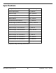
Specifications Lifting Capacity 1,500 lbs. / 680 kg Power Supply (Pump) Air / Hydraulic Platform Length 79.5" / 2,019 mm Platform Length w/ Extension 99.75" / 2,534 mm Platform Width 29.5" / 749 mm Overall Width with Side Decks 51" / 1,295 mm Overall Length w/ Extension and Ramp 134.75" / 3,422 mm Lowered Height 7.75" / 197 mm Platform Height – 1st Lock Position 24" / 610 mm Platform Height – 2nd Lock Position 28.75" / 730 mm Platform Height – 3rd Lock Position 32.
Installation This section describes how to prepare your ATV/Motorcycle Lift for normal operation. Perform the tasks in the order listed. Installation Safety Rules Pay attention at all times during installation. Use appropriate tools and equipment. Stay clear of moving parts. Keep hands and fingers away from pinch points. Safety is a top priority. Use caution when unpacking the Lift.
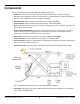
Clearances The drawing below shows the amount of space around the Lift to operate it effectively. ⚠ WARNING For safety purposes, only the operator should be within 30 feet /10 meters of the Lift during use. Not necessarily to scale. Not all components shown. BendPak Ranger recommends leaving an additional 12 inches / 305 mm of open space above the top of the Tie-Down Poles. RML-1500XL ATV / Motorcycle Lift 11 P/N 5900183 — Rev. E — Feb.
Unpack the Components Use caution when unpacking Lift components. You do not want to damage or misplace anything. Tip Consider unpacking the components in the area where you are going to set up the Lift. The fewer times you move the components, the fewer opportunities there are for them to get lost, get damaged, or damage the surface they are on. To unpack the Lift components: 1. Move the box holding the Lift as close as possible to where it will be used. 2.
Once the Hydraulic Hose is connected, you can use the Raising Pedal to raise the Lift. If you plan on using a pressurized Air Supply to raise the Lift and the Air Supply is nearby and ready, you can connect the Pneumatic Hose to the Air/Hydraulic Pump and then use the Raising Trigger to raise the Platform. ⚠ WARNING The Lift uses pneumatic (air) energy; if your organization has Lockout/Tagout policies, make sure to implement them once the Lift is connected to a pressurized Air Supply. 7.
Choose a Mode The Lift can be installed in either of two Modes: • Motorcycle Mode. For motorcycles only. In Motorcycle Mode, the Lift’s Platform is not wide enough to accommodate ATVs. To install the Lift in Motorcycle Mode, install the Cover and the Motorcycle Ramp, then bolt the Clamp Assembly onto the front of the Platform. If you are installing the Lift in Motorcycle Mode, do not install the two gray ATV Ramps, the Side Extensions, or the Front Extension.
Putting the Lift Components into Place The following procedure assumes you have unpacked the Lift components and decided on which Mode you want to use. If not, go back and do those things before proceeding. This section does not cover installing the Clamp Assembly; it is covered in the next section. RML-1500XL ATV / Motorcycle Lift 15 P/N 5900183 — Rev. E — Feb.
Refer to the drawing on the previous page during installation. To install Lift components: 1. Put the Cover into place at the Ramp end of the Lift. 2. Take the Front Extension and slide it over the non-Ramp end of the Lift. You can easily identify this end of the Lift because it has the drilled holes used later to install the Clamp Assembly. These hole are shown in the drawing on the previous page. Make sure to align the holes in the side of the Front Extension with the holes in the side of the Platform. 3.
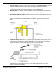
Installing the Clamp Assembly The Clamp Assembly holds the front tire of the ATV or Motorcycle in place while it is on the Lift. It includes three pieces, all of them yellow. The Tire Stop, which bolts onto the Platform, is also yellow. To install the Clamp Assembly and Tire Stop: 1. Locate the three pieces of the Clamp Assembly (Handle Assembly, Moveable Clamp Arm, and Bolted Clamp Arm), the Tire Stop, and 14 Bolts, Flat Washers, Split-Lock Washers, and Nuts.
Operation This section describes how to use the ATV/Motorcycle Lift safely during normal operation. Safety Rules Important: Your safety is dependent on reading, understanding, and implementing these Safety Rules. Do not skip over them; read them carefully and follow them! To use your ATV/Motorcycle Lift safely: • Before raising a vehicle, inspect the Lift every time. Check for kinked hoses, worn or missing parts, or any other abnormalities.
Raising a Vehicle The Platform is raised using the Air/Hydraulic Pump. To raise a vehicle: 1. Make sure you are wearing OSHA-approved (publication 3151) Personal Protective Equipment: leather gloves, steel-toed work boots, back belts, hearing protection, and ANSI-approved eye protection (safety glasses, face shield, or goggles). 2. Make sure the Platform is fully lowered, the area around the Lift is clear of any obstructions, and the Safety Lock Release Handle is in the lowered (Lock) position. 3.
⚠ CAUTION Do not raise the Platform past the top Safety Lock. In rare cases, the Safety Lock Plate can go too far and get stuck past the top Safety Lock. If this happens, manually lift the Safety Lock Plate to unstick it. 10. Use the Lowering Pedal to back the Platform down onto the most recently passed Safety Lock. 11. When the Platform stops moving, hold the Lowering Pedal down for several more seconds, then check to make sure the Safety Lock Plate is engaged on the Safety Lock.
Using the Casters The Lift has built-in Casters, making it easy to move the Lift to different locations. To move the Lift using the Casters: 1. Find a 10 mm hex key (also called an Allen® key or wrench). 2. Locate the four Caster Adjustment Rods on the Base of the Lift. The two Caster Adjustment Rods on the Ramp end of the Lift may be under the gray ATV Ramps if you have installed them already. 3. Turn each of the four Caster Adjustment Rods clockwise to engage the Casters.
Maintenance ⚠ WARNING Disconnect the Lift from its pressurized Air Supply (if connected) before performing any troubleshooting procedures. The Lift uses pneumatic (air) energy; if your organization has Lockout/Tagout policies, make sure to implement them once the Lift is connected to a pressurized Air Supply. To maintain your ATV/Motorcycle Lift: • • • Cleanliness. Make sure to keep the Lift clean and free of debris and dirt. Wipe it down after each use; remove any grease, dirt, or other debris.
Troubleshooting ⚠ WARNING Disconnect the Lift from its pressurized Air Supply (if connected) before performing any troubleshooting procedures. The Lift uses pneumatic (air) energy; if your organization has Lockout/Tagout policies, make sure to implement them once the Lift is connected to a pressurized Air Supply. Issue Action to Take Platform does not raise. Make sure you have a pressurized Air Supply attached or are using the Raising Pedal.
Labels RML-1500XL ATV / Motorcycle Lift 24 P/N 5900183 — Rev. E — Feb.
Parts Drawings # 1 2 3 4 5 6 7 8 9 10 11 12 13 14 15 16 Description M16 A110 Bolt, Nut, and Washer M14 A110 Bolt, Nut, and Washer 2 inch Caster Base Assembly Hydraulic Jack Pneumatic/Hydraulic Pump Bearing 1520 Link Rod 1 M20 A120 Bolt, Nylon Nut, and Washer Tire Bearing 2020 Link Rod 2 Ball Handle M16 A70 Bolt, Nut, and Washer M16 A370 Bolt and Washer Shoulder Right RML-1500XL ATV / Motorcycle Lift Quantity 1 1 4 1 1 1 6 1 2 4 8 1 1 1 6 1 25 P/N 5900183 — Rev. E — Feb.
17 18 19 20 21 22 23 24 25 26 27 28 29 30 31 32 33 34 35 36 37 38 39 40 41 42 43 44 45 46 47 48 49 50 51 52 53 54 55 56 57 58 M12 Nut and Washer U Bolt U Bolt M14 A80 Bolt, Nut, and Washer Base Clamp M12 A25 Bolt, Nut, and Lock Washer M8 A12 Bolt and Lock Washer Block Handle - Clamp Screw Rod Clamp Shoulder Left n/a M5 30 Bolt M8 Bolt, Nut, and Washer Nylon Tire Deck Plate, Moveable Lock Assembly Deck Plate M5 Lock Nut Deck Plate, main M6 A18 Bolt and Washer Safety Plate Safety Block Link Rod M8 Washer M8
Maintenance Log RML-1500XL ATV / Motorcycle Lift 27 P/N 5900183 — Rev. E — Feb.
1645 Lemonwood Drive Santa Paula, CA 93060 USA © 2020 BendPak Inc. All rights reserved. bendpak.