
User's Guide


Table Of Contents
- U110689 Cover
- U110689-03a [GB]
- 1. Before you start...
- 2. Cooker Overview
- 3. 2 Button - rotary clock
- 4. 6 Button clock
- 5. Cooking tips
- 6. Cooking Table
- 7. Cleaning Your Cooker
- 8. Troubleshooting
- 9. Installation
- Dear Installer
- Safety Requirements and Regulations
- Provision of Ventilation
- Location of Cooker
- Conversion
- Positioning the Cooker
- Moving the Cooker
- Lowering the Two Rear Rollers
- Completing the Move
- Fitting the Stability Bracket or Chain
- Repositioning the Cooker Following Connection
- Conversion to Another Gas
- Levelling
- Gas Connection
- Pressure Testing
- Electrical Connection
- Final Checks
- Final Fitting
- Customer Care
- 10. Conversion to LP Gas
- 11. Circuit Diagram
- 12. Technical Data
- BACK_RM 2018
35
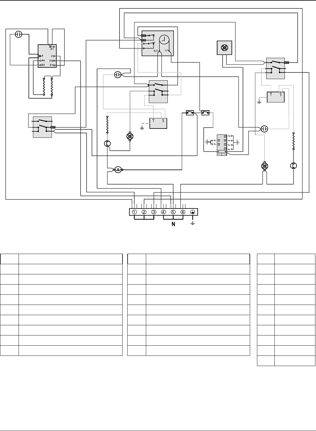
11. Circuit Diagram
P095199
2
P2
P1
1
P095199
2
P2
P1
1
a
b
e
f
c
d
1
2
b
v
br bbbb
r
b
b
r
b
b
br
v
bk
bk
v
v
br
br
b
y
y
y
y
br
b
br
b
br
b
bk
b
g/y
v
y
y
or
or
g/y
r
r
bk
br
br
v
bk
v
br
b
r
b
b
v
b
b
r
r
v
y
y
b
r
b
r
b
bbr br
br
b
b
y
br br b
br
v
v
y
E
X02
X17
X01
L
X27
X31
X05
X26
X26
X26
X27
X32
X14
X12
X15
X24
X04X03
X29
X30
P095199
2
P2
P1
1
X07
y
X09
b
or
b
X16
X16
or
Key
The connections shown in the circuit diagram are for single-phase. The ratings are for 230 V 50 Hz.
Code Colour
b
Blue
br
Brown
bk
Black
or
Orange
r
Red
v
Violet
w
White
y
Yellow
g/y
Green/yellow
gr
Grey
Code Description
X01
Grill front switch
X02
Grill energy control
X03
Left Hand Grill Element
X04
Right Hand Grill Element
X05
Left Hand Oven Thermostat
X07
Left Hand Oven Front Switch
X09
Left-hand oven element
X12
Right-hand oven thermostat
X14
Right-hand oven front switch
Code Description
X15
Right-hand oven element
X16
Oven fan
X24
Cooling fan
X26
Neon
X27
Thermal cut-out
X29
Ignition switch
X30
Spark generator
X31
Oven light
X32
Oven light switch