Britain’s No.
CUSTOMER SERVICES GUARANTEE Rangemaster range cookers come with a 1 year parts & labour guarantee. You will receive an additional FREE full 12 months guarantee by registering your purchase using the FREEPOST form provided. Alternatively, call free on 0800 587 5747, quoting reference RMGX57A, or register online at www.rangemaster.co.uk.
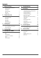
Contents 1. 2. 3. Before You Start... 1 6. Troubleshooting 22 Installation and Maintenance 1 Peculiar Smells 1 7.
ii
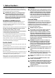
1. Before You Start... Ventilation Your cooker should give you many years of trouble-free cooking if installed and operated correctly. It is important that you read this section before you start, particularly if you have not used an induction cooker before. CAUTION: The use of a cooking appliance results in nn the production of heat and moisture in the room in which it is installed.
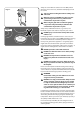
Always be certain that the controls are in the OFF position when the oven is not in use, and before attempting to clean the cooker. Fig. 1-1 Take care when touching the marked cooking areas nn of the hob. When the oven is on, DO NOT leave the oven door nn open for longer than necessary, otherwise the ArtNo.324-0001 Steam burst control knobs may become very hot. When using the grill, make sure that the grill pan nn is in position and pushed fully in, otherwise the control knobs may become very hot.
DO NOT use water on grease fires and never pick nn up a flaming pan. Turn off the controls and then Fig. 1-3 smother a flaming pan on a surface unit by covering the pan completely with a well fitting lid or baking tray. If available, use a multi-purpose dry chemical or foam-type fire extinguisher. Take care that no water seeps into the appliance. This appliance is heavy so take care when moving it. nn Hob Care NEVER allow anyone to climb or stand on the hob.
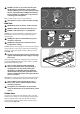
2. Cooker Overview DocNo.025-0012 - Overview - 110 ceramic - Elan Fig. 2.1 A B C D E F Your induction cooker (Fig.2-1) has the following features: Fig. 2.2 A. B. C. D. E. F. 5 induction cooking zones Control panel Glide-out grill Slow cook oven Programmable multifunction oven Fan oven The Hob Use only pans that are suitable for induction hobs. We recommend stainless steel, enamelled steel pans or cast iron pans with enamelled bases.
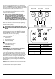
The very best pans have bases that are very slightly curved up when cold (Fig.2-3). If you hold a ruler across the bottom you will see a small gap in the middle. When they heat up the metal expands and lies flat on the cooking surface. Fig. 2.4 Max: 1.85 kW Boost: 2.5 kW Max: 1.85 kW Boost: 3.0 kW Max: 1.85 kW Boost: 2.5 kW Zone 1 Zone 3 Zone 5 Make sure that the base of the pan is clean and dry to prevent any residue burning onto the hob panel. This also helps prevent scratches and deposits.
Residual Heat Indicator, H Power Level Automatic Heat-up Time at 100% (min:sec) 1 0:48 2 2:24 3 3:50 4 5:12 5 6:48 Automatic Heat-up, A 6 2:00 7 2:48 8 3:36 This function is available on all of the cooking zones. It allows rapid heating up of the element to bring the selected cooking zone up to temperature. Once the zone is at the required cooking temperature the power level will reduce automatically to the preset level.
Low Temperature Setting, L1/L2 • • Fig. 2.8 A & B linked Each cooking area is equipped with 2 low temperature settings: L1 will maintain a temperature of about 40 °C – ideal for gently melting butter or chocolate. L2 will maintain a temperature of about 90 °C – ideal for simmering (bring the pan to the boil and then select L2 to keep soups, sauces, stews, etc at an optimal simmer). A B D The maximum time this setting can be used is 2 hours.
The Glide-out Grill Fig. 2.9 CAUTION: This appliance is for cooking purposes nn only. It must not be used for other purposes, for example room heating. CAUTION: Accessible parts may be hot when the grill nn is in use. Young children should be kept away. Open the door and pull the grill pan carriage forward using the handle (Fig.2-9). ArtNo.331-0001Grill pan pulled forwards The grill has two elements that allow either the whole area of the pan to be heated or just the right-hand half. Fig. 2.
Fan Oven This function operates the fan and the heating element around it. An even heat is produced throughout the oven, allowing you to cook large amounts quickly. The Ovens The clock must be set to the time of day before the lefthand oven will work. See the following section on ‘The Clock’ for instructions on setting the time of day. References to ‘left-hand’ and ‘right-hand’ ovens apply as viewed from the front of the appliance.
Conventional Oven (Top and Base Heat) This function combines the heat from the top and base elements. It is particularly suitable for roasting and baking pastry, cakes and biscuits. The Fan Oven Fan ovens circulate hot air continuously, which means faster, more even cooking. The recommended cooking temperatures for a fan oven are generally lower than those for a non-fan oven.
Operating the Ovens Fig. 2.12 Fan Oven Turn the oven knob to the desired temperature (Fig. 2.12). The oven indicator light will glow until the oven has reached the temperature selected. It will then cycle on and off during cooking. Multifunction Oven The multifunction oven has two controls: a function selector and a temperature setting knob (Fig. 2.13). Turn the function selector control to a cooking function. Turn the oven temperature knob to the temperature required (Fig. 2.14).
The Clock Fig. 2.16 The clock must be set to the time of day before the oven will work. ArtNo.300-0005 2BC minute minder setting 1. Once the cooker is connected and switched on, the display will start to flash. C A 2. To set the time, turn and hold the Timer (A) knob to the Clock (C) setting and at the same time turn the Adjusting (B) knob either clockwise or counter-clockwise (Fig. 2.16). B 3. Once you have set the time release the Timer (A) knob. A – Timer knob, B – Adjusting knob Fig. 2.
To Stop the Multifunction Oven at a Specific Time of Day ArtNo.301-0008 2BC Stopping the oven 2 You have set the required temperature and function mode for the Multifunction Oven and you would like the Multifunction Oven to automatically stop. Fig. 2.21 G TOP TIP A Make a note of the current time so you do not forget. B ArtNo.301-0008 2BC Stopping the oven 2 1. Turn the Timer (A) knob to the Stop Time (G) setting (Fig. 2.21). Fig. 2.22 2.
To Start and Stop the Multifunction Oven ArtNo.301-0010 2BC Setting the cooking time Fig. 2.24 The Multifunction Oven allows you to automatically start and stop by a combination of the length of the cooking time and the stop time. Giving you the flexibilty to cook casseroles etc while you are out. You cannot set the actual start time. F A 1. Turn the Timer (A) knob to the Cook Time (F) setting. Turn the Adjusting (B) knob clockwise to set the length of the cooking time required e.g. 50 seconds (Fig. 2.
Accessories Fig. 2.31 Oven Shelves – Left-hand (Main) Oven Shelf guard The oven shelves (Fig. 2.31) are retained when pulled forward but can be easily removed and refitted. Pull the shelf forward until the back of the shelf is stopped by the shelf stop bumps in the oven sides (Fig. 2.32). Lift up the front of the shelf so the back of the shelf will pass under the shelf stop and then pull the shelf forward (Fig. 2.33). Front Fig. 2.
3. Cooking Tips WARNING! Refer to Before You Start... chapter. Hints on Using Your Induction Cooker General Oven Tips If you have not used an induction cooker before please be aware of the following: The wire shelves should always be pushed firmly to the back of the oven. • Baking trays with food cooking on them should be placed level with the front edge of the oven’s wire shelves. Other containers should be placed centrally.
4. Cooking Table DocNo.031-0004 - Cooking table - electric & fan single cavity The oven control settings and cooking times given in the table below are intended to be used AS A GUIDE ONLY. Individual tastes may require the temperature to be altered to provide a preferred result. Food is cooked at lower temperature in a fan oven than in a conventional oven. When using recipes, reduce the fan oven temperature by 10 °C and the cooking time by 5-10 minutes.
5. Cleaning Your Cooker DocNo.045-0017 - Cleaning - 110 Classic - tpl glzd & std grill Essential Information Fig. 5.1 Isolate the electricity supply before carrying out any major cleaning. Then allow the cooker to cool. NEVER use paint solvents, washing soda, caustic nn cleaners, biological powders, bleach, chlorine based bleach cleaners, coarse abrasives or salt. DO NOT mix different cleaning products – they may nn react together with hazardous results.
Cleaning Burned-on Spills Fig. 5.2 Make sure that the heat indicator lights are off and that the hob is cool. Remove the excess burned-on substance with a single-edged razor scraper. Hold the scraper at an angle of about 30° to the surface and then scrape off the burned-on matter (Fig. 5.1). Once you have removed as much as possible with the scraper, follow the ‘Daily Care’ procedure outlined above. To Remove Metal Rub-off ArtNo.331-0001Grill pan pulled forwards Fig. 5.
Control Panel and Doors Fig. 5.7 Avoid using any abrasive cleaners, including cream cleaners, on the control panel. For best results, use a liquid detergent. The same cleaner can also be used on the doors. Alternatively, use a soft cloth wrung out in clean hot soapy water. You can use the same method for cleaning the control panel and knobs. After cleaning, polish with a dry cloth. Glass Fronted Door Panels ArtNo.
Cleaning Table Cleaners listed (Table 5-1) are available from supermarkets or electrical retailers as stated. For enamelled surfaces use a cleaner that is approved for use on vitreous enamel. Regular cleaning is recommended. For easier cleaning, wipe up any spillages immediately. Hotplate Part Finish Recommended Cleaning Method Hob top Enamel or stainless steel Hot soapy water, soft cloth. Any stubborn stains remove gently with a nylon scourer.
6. Troubleshooting DocNo.050-0001 - Troubleshooting - Induction GENERIC The cooling fan The induction hob incorporates a cooling fan. This cooling fan is active when either the grill or ovens are on. Under certain conditions, the cooling fan may remain active when the grill or ovens are switched off. This is normal and the fan will switch off automatically. Interference with and repairs to the hob MUST NOT nn be carried out by unqualified persons.
Food is cooking too slowly, too quickly, or burning Cooking times may differ from your previous oven. Check that you are using the recommended temperatures and shelf positions – see the oven cooking guide. Then adjust the settings according to your own individual tastes. Fig. 6-1 ArtNo.324-0005 Oven light bulb The oven is not cooking evenly Do not use a baking tray with dimensions larger than those specified in the section on ‘General Oven Tips’. Fig.
The oven light is not working The bulb has probably blown. You can buy a replacement bulb (which is not covered under the guarantee) from most electrical stores. Ask for an Edison screw fitting 15 W 230 V lamp, FOR OVENS (Fig.6-1). It must be a special bulb, heat resistant to 300 °C. Fig. 6-3 Before removing the existing bulb, turn off the power supply and make sure that the oven is cool. Open the oven door and remove the oven shelves. ArtNo.
INSTALLATION Check the appliance is electrically safe when you have finished. 7. Installation DocNo.066-0003 - Installation - 110 Ceramic - Excel You will need the following equipment to complete the cooker installation satisfactorily: • Multimeter (for electrical checks). You will also need the following tools: 1. Steel tape measure 2. Cross-head screwdriver 3. Flat-bladed screwdriver 4. Spirit level 5. Pencil 6. Adjustable spanner 7.
INSTALLATION Check the appliance is electrically safe when you have finished. Positioning the Cooker Fig. 7.1 Fig.7-1 and Fig.7-2 show the minimum recommended distance from the cooker to nearby surfaces. 75 mm min The cooker should not be placed on a base. 650 mm min The hotplate surround should be level with, or above, any adjacent work surface. A gap of 75 mm should be left between each side of the cooker ABOVE the hotplate level and any adjacent vertical surface.
INSTALLATION Check the appliance is electrically safe when you have finished. Lowering the Two Rear Rollers Fig. 7.5 To adjust the height of the rear of the cooker, first fit a 13 mm spanner or socket wrench onto the hexagonal adjusting nut (Fig.7-5). Rotate the nut – clockwise to raise – counter-clockwise to lower. Make 10 complete (360°) turns clockwise. Make sure you lower BOTH REAR ROLLERS. Completing the Move Unfold the rear edge of the cardboard base tray.
INSTALLATION Check the appliance is electrically safe when you have finished. Electrical Connection Current Operated Earth Leakage Breakers The combined use of your cooker and other domestic appliances may cause nuisance tripping, so we recommend that the cooker is protected on an individual RCD (Residual Current Device) or RCBO (Residual Current Breaker with Overload).
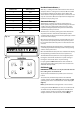
8. Circuit Diagrams Circuit Diagram: Hob E 5 4 3 2 1 Induction unit Earth N(6) On terminal block N(4) On terminal block Hob display ArtNo.083-0011 - IN G5 2-phase - Circuit diagram w/br w/br 1 2 1 2 Interface 5 w/br board 3 4 w/br 5 3 L(2) L(3) On terminal block w/br 4 Key The connections shown in the circuit diagram are for single-phase. The ratings are for 230 V 50 Hz.
Circuit Diagram: Oven K b r K bk bk K B2a b A1 K r b br J A2 v b b b br 3 bk 2 P4 A3 P3 br b r br w H y br B3 B4 Jb r gr B5 B7 gr 8 o r w B6 w y o o bk y o br P2 1 P1 6 v r P6 w 5 P5 4 P4 3 P3 K w b w w y F1 P8 v G y 4 o 3 P2 y P1 y 1 b D3 P7 2 P038434 P3 I b P033458 F2 P2 v 1 P1 br b b br o F4 bk br F3 v P033458 bk br br br br 2 v P1 w P4 P2 y 1 br D2 r r B2 7 2 P095199 bk b b b b b b bk v B1 w b r
DocNo.103-0019 - Technical data - 110 Induction - G5 Excel 9. Technical Data INSTALLER: Please leave these instructions with the user. DATA BADGE LOCATION: Cooker back, serial number repeater badge below the oven door opening. COUNTRY OF DESTINATION: GB, IE, FR, NL, DE, SE, BE, AT, CH, LU.
Hotplate Efficiency Data Brand Rangemaster Model Identification Excel Size 110 Type Induction Type of Hob Induction Number of electric zones 5 Zone 1 - Ø cm 18.5 Heating Technology Energy Consumption (ECElectric cooking) - Wh/kg 172 Zone 2 - Ø cm 15.5 Heating Technology Energy Consumption (ECElectric cooking) - Wh/kg 180 Zone 3 - Ø cm 18.5 Heating Technology Energy Consumption (ECElectric cooking) - Wh/kg 172 Zone 4 - Ø cm 15.
Oven Data Brand Rangemaster Model identification Excel Type of oven Electric Mass kg 136 Number of cavities 2 Left-hand Efficiency Fuel type Electric Cavity type Multifunction Power - conventional 2.2 Power - forced air convection 2.5 Volume Litres 73 Energy consumption (electricity) - conventional kWh / cycle 1.08 Energy consumption (electricity) - forced air convection kWh / cycle 0.91 Energy efficiency index - conventional 126.
Notes 34
hobs must be reported within 14 days. Scratches caused by usage are not covered. Accidental damage is not covered by the manufacturer’s warranty. Name of Appliance & Colour* For warranty compliance, the requirements for the appliance are: • Has been correctly installed in accordance with current legislation, relevant British and European Standards and Codes of Practice, by a suitably competent person registered with Gas Safe or equivalent body and where applicable a qualified electrician.
ALSO PART OF THE RANGEMASTER COLLECTION... Refrigeration Built-in Cooking Dishwashing Sinks & Taps Clarence Street Royal Leamington Spa Warwickshire CV31 2AD England Tel: +44 (0) 1926 457400 Fax: +44 (0)1926 450526 E-mail: consumers@rangemaster.co.uk Consumer Services Tel: +44 (0) 800 804 6261 www.rangemaster.co.uk Britain’s No.1 Range Cooker For ROI Enquiries Tel: 1850 302 502 Search Rangemaster UK Registered in England and Wales. Registration No.