® R&S RTM3000 Oscilloscope Getting Started (=Sèâ2) 1335908402 Version 06
This manual describes the following R&S®RTM3000 models: ● R&S®RTM3002 (1335.8794K02) ● R&S®RTM3004 (1335.8794K04) © 2021 Rohde & Schwarz GmbH & Co. KG Mühldorfstr. 15, 81671 München, Germany Phone: +49 89 41 29 - 0 Email: info@rohde-schwarz.com Internet: www.rohde-schwarz.com Subject to change – data without tolerance limits is not binding. R&S® is a registered trademark of Rohde & Schwarz GmbH & Co. KG. Trade names are trademarks of the owners. 1335.9084.
R&S®RTM3000 Contents Contents 1 Safety and regulatory information....................................... 5 1.1 Safety instructions................................................................................5 1.2 Labels on the product.........................................................................11 1.3 Warning messages in the documentation........................................ 12 1.4 Korea certification class A.................................................................
R&S®RTM3000 Contents 4.2 Side view..............................................................................................23 4.3 Rear view............................................................................................. 24 5 Contacting customer support............................................ 26 Getting Started 1335.9084.
R&S®RTM3000 Safety and regulatory information Safety instructions 1 Safety and regulatory information The product documentation helps you to use the product safely and efficiently. Follow the instructions provided here and in the Chapter 1.1, "Safety instructions", on page 5. Intended use The R&S RTM3000 oscilloscope is designed for measurements on circuits that are only indirectly connected to the mains or not connected at all. It is not rated for any measurement category.
R&S®RTM3000 Safety and regulatory information Safety instructions Using the product requires specialists or specially trained personnel. These users also need sound knowledge of at least one of the languages in which the user interfaces and the product documentation are available. Never open the casing of the product. Only service personnel authorized by Rohde & Schwarz are allowed to repair the product. If any part of the product is damaged or broken, stop using the product.
R&S®RTM3000 Safety and regulatory information Safety instructions Setting up the product Always place the product on a stable, flat and level surface with the bottom of the product facing down. If the product is designed for different positions, secure the product so that it cannot fall over. If the product has foldable feet, always fold the feet completely in or out to ensure stability. The feet can collapse if they are not folded out completely or if the product is moved without lifting it.
R&S®RTM3000 Safety and regulatory information Safety instructions ● Only use intact cables and route them carefully so that they cannot be damaged. Check the power cables regularly to ensure that they are undamaged. Also ensure that nobody can trip over loose cables. ● If the product needs an external power supply, use the power supply that is delivered with the product or that is recommended in the product documentation or a power supply that conforms to the country-specific regulations.
R&S®RTM3000 Safety and regulatory information Safety instructions tweezers or pliers to avoid injuries. When transporting the accessories, always use the box supplied with the probe. ● Prevent the probe from receiving mechanical shock. Avoid putting excessive strain on the probe cable or exposing it to sharp bends. Touching a broken cable during measurements can cause injuries. ● Set up all probe connections to the instrument before applying power.
R&S®RTM3000 Safety and regulatory information Safety instructions ● The following effects can cause burns and fire or damage to the measurement site: – Eddy current loss can cause heating of the sensor head. – Dielectric heating can cause heating of cord insulation and other materials. Measurement categories IEC 61010-2-030 defines measurement categories that rate instruments on their ability to resist short transient overvoltages that occur in addition to the working voltage.
R&S®RTM3000 Safety and regulatory information Labels on the product Cleaning the product Use a dry, lint-free cloth to clean the product. When cleaning, keep in mind that the casing is not waterproof. Do not use liquid cleaning agents. Meaning of safety labels Safety labels on the product warn against potential hazards. Potential hazard Read the product documentation to avoid personal injury or product damage. Electrical hazard Indicates live parts.
R&S®RTM3000 Safety and regulatory information Korea certification class A 1.3 Warning messages in the documentation A warning message points out a risk or danger that you need to be aware of. The signal word indicates the severity of the safety hazard and how likely it will occur if you do not follow the safety precautions. WARNING Potentially hazardous situation. Could result in death or serious injury if not avoided. CAUTION Potentially hazardous situation.
Documentation overview R&S®RTM3000 Manuals and instrument help 2 Documentation overview This section provides an overview of the R&S RTM3000 user documentation. 2.1 Manuals and instrument help You find the manuals on the product page at: www.rohde-schwarz.com/manual/rtm3000 Getting started manual Introduces the R&S RTM3000 and describes how to set up the product. A printed English version is included in the delivery. User manual Contains the description of all instrument modes and functions.
Documentation overview R&S®RTM3000 Release notes and open source acknowledgment Service manual Describes the performance test for checking the rated specifications, module replacement and repair, firmware update, troubleshooting and fault elimination, and contains mechanical drawings and spare part lists. The service manual is available for registered users on the global Rohde & Schwarz information system (GLORIS, https://gloris.rohde-schwarz.com). 2.
R&S®RTM3000 Preparing for use Unpacking and checking 3 Preparing for use Here, you can find basic information about setting up the instrument for the first time or when changing the operating site. 3.1 Lifting and carrying See: "Lifting and carrying the instrument" on page 6. 3.2 Unpacking and checking 1. Unpack the product carefully. 2. Retain the original packing material. Use it when transporting or shipping the product later. 3. Using the delivery notes, check the equipment for completeness.
Preparing for use R&S®RTM3000 Setting up the product 3.3 Choosing the operating site Specific operating conditions ensure proper operation and avoid damage to the product and connected devices. For information on environmental conditions such as ambient temperature and humidity, see the data sheet. See also "Choosing the operating site" on page 6. Electromagnetic compatibility classes The electromagnetic compatibility (EMC) class indicates where you can operate the product.
R&S®RTM3000 Preparing for use Setting up the product To place the product on a bench top 1. Place the product on a stable, flat and level surface. Ensure that the surface can support the weight of the product. For information on the weight, see the data sheet. 2. CAUTION! Foldable feet can collapse. See "Setting up the product" on page 7. Always fold the feet completely in or out. With folded-out feet, do not place anything on top or underneath. 3. CAUTION! The product can fall over and cause injury.
Preparing for use R&S®RTM3000 Considerations for test setup Design and implement an efficient ventilation concept for the rack. To mount the R&S RTM3000 in a rack 1. Use an adapter kit that fits the dimensions of the R&S RTM3000 to prepare the instrument for rack mounting. For information on the dimensions, see data sheet. a) Order the rack adapter kit designed for the R&S RTM3000. For the order number, see data sheet. b) Mount the adapter kit.
R&S®RTM3000 Preparing for use Connecting to power Measuring accessories Use only probes and measuring accessories that comply with IEC 61010-031. Signal input and output levels Information on signal levels is provided in the data sheet. Keep the signal levels within the specified ranges to avoid damage to the product and connected devices. Preventing electrostatic discharge (ESD) Electrostatic discharge is most likely to occur when you connect or disconnect a DUT.
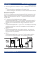
R&S®RTM3000 Preparing for use Changing fuses 1. Plug the AC power cable into the AC power connector on the rear panel of the product. Only use the AC power cable delivered with the product. 2. Plug the AC power cable into a power outlet with ground contact. The required ratings are listed next to the AC power connector and in the data sheet. 3.7 Changing fuses If the product does not start, it is possible that a blown fuse is the cause.
R&S®RTM3000 Instrument tour Front view 4 Instrument tour 4.1 Front view Figure 4-1 shows the front panel of the R&S RTM3000. The function keys are grouped in functional blocks to the right of the display.
R&S®RTM3000 Instrument tour Front view The R&S RTM3002 has 2 input channels, and the R&S RTM3004 has 4 input channels. 4.1.1 Input connectors BNC inputs (4 and 5) The R&S RTM3000 has two or four channel inputs (4) to connect the input signals. The external trigger input (5) is used to control the measurement by an external signal. The trigger level can be set from -5 V to 5 V. For channel connectors, the input impedance is selectable, the values are 50 Ω and 1 MΩ.
Instrument tour R&S®RTM3000 Side view [Pattern Generator] (8) Connectors for the pattern generator P0, P1, P2, P3. [Probe Comp.] (9) Probe compensation terminal to support adjustment of passive probes to the oscilloscope channel. Square wave signal for probe compensation. Ground connector for probes. [USB] type A (10) USB 2.0 type A interface to connect a mouse or a keyboard, or a USB flash drive for storing and reloading instrument settings and measurement data, and to update the firmware. 4.
R&S®RTM3000 Instrument tour Rear view Logic probe The connectors for logic channels can be used if the Mixed Signal Option R&S RTM-B1 is installed. The option provides connectors for two logical probes with 8 digital channels each (D0 to D7 and D8 to D15). The maximum input voltage is 40 V (peak) at 100 kΩ input impedance. The maximum input frequency for a signal with the minimum input voltage swing and medium hysteresis of 800 mV (Vpp) is 400 MHz. 4.
R&S®RTM3000 Instrument tour Rear view 5 = Kensington lock slot to secure the instrument against theft 6 = Loop for lock to secure the instrument against theft 7 = not used [Aux Out] (1) Multi-purpose BNC output that can function as pass/fail and trigger output, and output of 10 MHz reference frequency. [USB] type B (2) USB 2.0 interface of type B (device USB) for remote control of the instrument. [LAN] (3) 8-pin connector RJ-45 used to connect the instrument to a Local Area Network (LAN).
R&S®RTM3000 5 Contacting customer support Contacting customer support Technical support – where and when you need it For quick, expert help with any Rohde & Schwarz product, contact our customer support center. A team of highly qualified engineers provides support and works with you to find a solution to your query on any aspect of the operation, programming or applications of Rohde & Schwarz products. Contact information Contact our customer support center at www.rohde-schwarz.