
Installation Guide


6
III. Water Piping and Trim
WARNING
Failure to properly pipe boiler may result in
improper operation and damage to boiler or
building.
A. Design and install boiler and system piping to
prevent oxygen contamination of boiler water.
Oxygen contamination sources are system leaks
requiring addition of makeup water, ttings, and
oxygen permeable materials in distribution system.
Eliminate oxygen contamination by repairing system
leaks, repairing ttings, and using non-permeable
materials in distribution system.
B. Install circulator with anges, gaskets and bolts
provided.
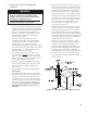
C. Install Safety Relief Valve. Safety Relief Valve must
be installed with spindle in vertical position.
WARNING
Safety relief valve discharge piping must be piped
near oor to eliminate potential of severe burns.
Do not pipe in any area where freezing could
occur. Do not install any shut-off valves.
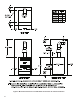
D. Connect system supply and return piping to boiler.
Refer to Figures 4 and 5. Also consult Residential
Hydronic Heating Installation and Design I=B=R
Guide. Maintain minimum ½ inch clearance from hot
water piping to combustible materials.
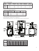
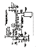
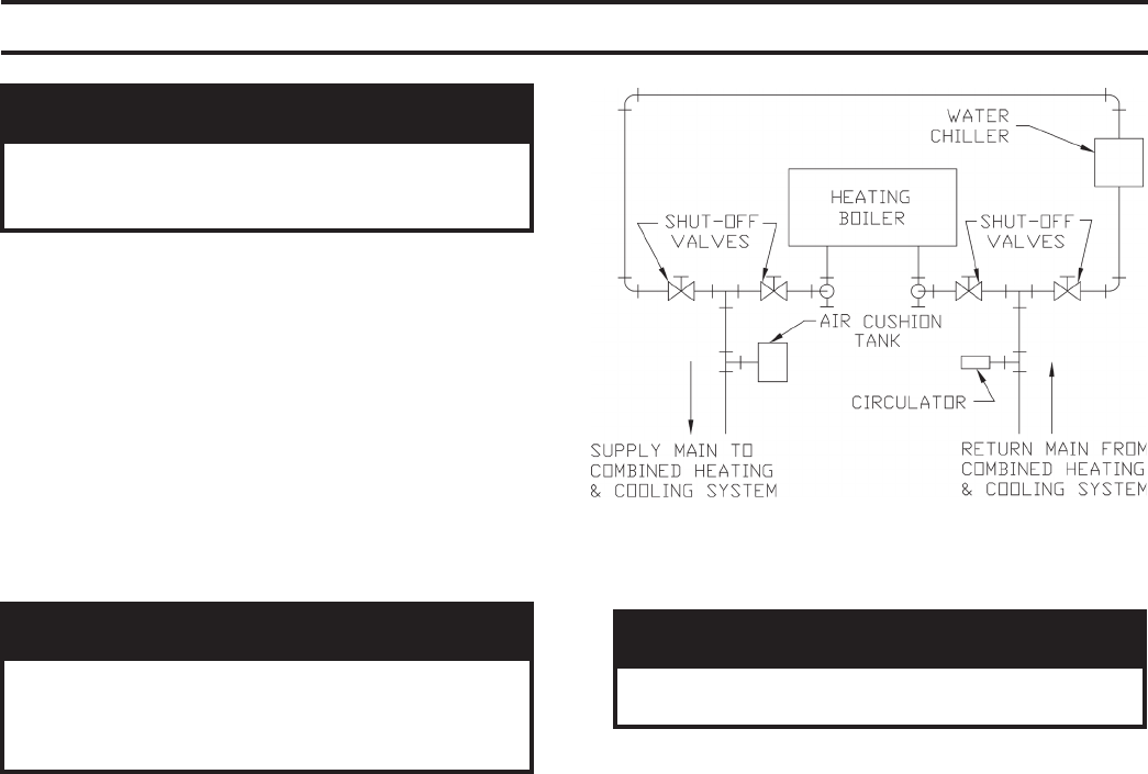
E. If boiler is used in connection with refrigeration
systems, boiler must be installed with chilled medium
piped in parallel with the heating boiler using
appropriate valves to prevent chilled medium from
entering boiler. See Figure 3. Also consult Residential
Hydronic Heating Installation and Design I=B=R
Guide.
F. If boiler is connected to heating coils located in
air handling units where they may be exposed to
refrigerated air, boiler piping must be equipped with
ow control valves or other automatic means to prevent
gravity circulation of boiler water during operation of
cooling system.
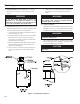
G. Use a boiler bypass if the boiler is to be operated
in a system which has a large volume or excessive
radiation where low boiler water temperatures may be
encountered (i.e. converted gravity circulation system,
etc.).
CAUTION
Boiler return water cannot be lower than 130°F for
proper function.
Install bypass between boiler supply and return in near
boiler piping as shown in Figures 4 and 5. Bypass
should be same size as the supply and return lines with
valves located in bypass and supply outlet as illustrated
in Figures 4 and 5 in order to regulate water ow to
maintain higher boiler water temperatures.
Set by-pass and boiler supply valves to half throttle
position to start. Operate boiler until system water
temperature reaches normal operating range.
Adjust valves to provide 180° to 200°F supply water
temperature. Opening the boiler supply valve will raise
system temperature, while opening by-pass valve will
lower system supply temperature.
H. If it is required to perform a long term pressure
test of the hydronic system, the boiler should rst be
isolated to avoid a pressure loss due to the escape of air
trapped in the boiler.
To perform a long term pressure test including the
boiler, ALL trapped air must rst be removed from the
boiler.
A loss of pressure during such a test, with no visible
water leakage, is an indication that the boiler contained
trapped air.
Figure 3: Recommended Piping for Combination
Heating & Cooling (Refrigeration) Systems