
Installation Guide


11
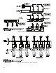
1. The vent damper must be the same size as the outlet
of the Draft Hood supplied with the boiler (see
Table 1A). Unpack the damper carefully - DO NOT
FORCE IT CLOSED! Forcing the damper may
damage the gear train and void the warranty.
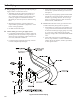
2. Mount the vent damper assembly onto the canopy/
diverter. (Refer to Figure 7 and to instructions
packed with the vent damper for specic
instructions). Do not modify either the draft hood or
vent damper.
NOTICE
Provide adequate clearance for servicing.
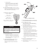
3. Locate vent damper position indicating means to be
visible following installation.
WARNING
Provide 6" minimum clearance between damper
and combustible construction.
4. Plug the factory harness vent damper connector into
damper motor polarized receptacle.
DANGER
Inspect existing chimney before installing boiler.
Failure to clean or replace perforated pipe or tile
lining will cause severe injury or death.
D. Inspect chimney and remove any obstructions or
restric tions. Clean chimney if previously used for solid
or liquid fuel-burning appliances or replaces.
E. Install vent system in accordance with "Venting of
Equipment" of the National Fuel Gas Code, ANSI
Z223.1/NFPA 54, or applicable provisions of local
building codes. The RRG Series boiler is a Category I,
draft hood equipped appliance.
WARNING
F. If an Existing Boiler is Removed:
When an existing boiler is removed from a common
venting system, the common venting system is likely
to be too large for proper venting of the appliances
remaining connected to it.
At the time of removal of an existing boiler, the
following steps shall be followed with each appliance
remaining connected to the common venting system
placed in operation, while the other appliances
remaining connected to the common venting system are
not in operation:
a. Seal any unused openings in the common venting
system.
b. Visually inspect the venting system for proper
size and horizontal pitch and determine there is no
blockage or restriction, leakage, corrosion, and other
deciencies which could cause an unsafe condition.
c. Insofar as is practical, close all building doors and
windows and all doors between the space in which
the appliances remaining connected to the common
venting system are located and other spaces of the
building. Turn on clothes dryers and any appliance
not connected to the common venting system.
Turn on any exhaust fans, such as range hoods and
bathroom exhausts, so they will operate at maxi mum
speed. Do not operate a summer exhaust fan. Close
replace dampers.
d. Place in operation the appliance being inspected.
Follow the Lighting (or Operating) Instructions.
Adjust thermo stat so appliance will operate
continuously.
e. Test for spillage at the draft hood relief opening after
5 minutes of main burner operation. Use the ame
of a match or candle, or smoke from a cigarette,
cigar or pipe.
f. After it has been determined that each appliance
remain ing connected to the common venting system
properly vents when tested as outlined above, return
doors, win dows, exhaust fans, replace dampers and
any other gas-burning appliance to their previous
condition of use.
g. Any improper operation of the common venting
system should be corrected so the installation
conforms with the National Fuel Gas Code, ANSI
Z223.1/NFPA 54. When resizing any portion of
the common venting system, the common venting
system should be resized to approach the minimum
size as determined using the appropriate tables in
Chapter 13 of the National Fuel Gas Code, ANSI
Z223.1/NFPA 54.