
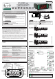
Product Overview

F43 - Time for functions lock:
It configures the time in seconds for the command to activate the functions lock:
[,,15] to [,,60] - Time in seconds for the command to activate the lock.
F44 - Control functions shutdown:
Authorizes switching off the control functions (see item 6.3.7).
[,,,0]- Disables the control functions shutdown.
[,,,1]- Enables activation/deactivation of the control functions only if the functions are unlocked.
[,,,2]- Enables activation/deactivation of the control functions even if the functions are locked.
F45 - Endereço do instrumento na rede RS-485:
Equipment's network address for communicating with Sitrad software.
NOTE: One network must not have different equipment with the same address.
F46 - Stage control mode:
It allows configuration for the operating mode of the stages, which can be normal or independent mode
(F46=0) or rotation mode (F46=1, 2, or 3). The rotation mode switches the output used for refrigeration,
making each machine work during a certain time and therefore makes all of them accumulate the same
working time (SEE item 6.3.16).
[,,,0]- Disables refrigeration in rotation mode.
[,,,1]- Enables rotation for OUT1 and OUT2.
[,,,2]- Enables rotation for OUT1, OUT2 and OUT3.
[,,,3]- Enables rotation for OUT1, OUT2, OUT3 and OUT4.
F47 - Time for rotation operation:
[,,,1] to [,999]- Time in hours for the rotation. When the current output accumulates this
activated time, it is switched off and the next output with less accumulated time is switched on.
NOTE: This function is only used if F46=1, 2, or 3.
F48 - Maximum time to activate a new output:
[,,,1] to [,999]- Time in minutes to activate a new output. When the output of the first stage
cannot reach the setpoint during this time another output is activated. If the rotation is enabled for the
three or four outputs the time counting is restarted too. If the established limit is exceeded again, without
the temperature reaching the setpoint, the next output is activated.
F49 - Minimum time between activations of relays:
[,,,0] - The relays will activate at the same time when required.
[,,,1] to [,999]- Time in seconds between the activation of relays.
This configuration is disregarded when the output works as an alarm or cyclical timer.
F50 - Time base for door open alarm:
[,,,0] - Seconds
[,,,1] - Minutes
F51 - Time for door open alarm:
When the door open alarm is enabled, the buzzer will be activated after the door is left open for the
programmed time. The time the buzzer will remain on and off for is configured in F26 and F27.
[OFF,] - Disabled.
[,,,1] to [,999]- Time to activate the door open alarm.
NOTE: It is also possible to link the door open alarm to the alarm output. For this, stage 4 must be
configured as alarm (F30=2, 3, or 4) and F52=2 or 3.
F52 - Digital input operating mode:
Configure which state of the digital input indicates the door is open:
[,,,0]- Closed contact indicates that the door is open
[,,,1]- Open contact indicates that the door is open..
[,,,2]- Contact closed indicates that the door is open and links the door open alarm to the alarm
output.
[,,,3]- Contact open indicates that the door is open and links the door open alarm to the alarm
output.
F53 - Stage 1 setpoint ([SP1,]):
Configures the desired temperature for stage 1.
F54 - Stage 2 setpoint ([SP2,]):
Configures the desired temperature for stage 2.
F55 - Stage 3 setpoint ([SP3,]):
Configures the desired temperature for stage 3.
F56 - Stage 4 setpoint ([SP4,]):
Configures the desired temperature for stage 4.
F57 - Maximum operating time of the outputs for maintenance:
Whenever the outputs are active (except the output configured as alarm), the instrument will record the
corresponding operating time. When this recorded time is equal to or higher than the time adjusted in
this function, the message [Man1] will be displayed for output 1, [Man2] for output 2, [Man3] for
output 3 or [Man4] for output 4, and the audible warning will also be activated, signaling that
maintenance is due in the corresponding output.
F58 - Enable HACCP alarm records:
Enable HACCP alarm recording as described in item 6.3.17.
[,,,0] - Disable
[,,,1] - Enable
F59 - HACCP - Low temperature alarm:
It is the temperature below which the instrument will create a HACCP record type [ALLo], as
described in item 6.3.17. This configuration is used only for HACCP records; it does not generate an
alarm in the alarm output and in the buzzer, because the values related to these specific alarms are
configured in the respective functions.
F60 - HACCP - High temperature alarm:
It is the temperature over which the instrument will create a HACCP record type [ALHi], as described
in item 6.3.17. This configuration is used only for HACCP records, it does not generate an alarm in the
alarm output and in the buzzer, because the values related to these specific alarms are configured in the
respective functions.
F61 - HACCP - Alarm validation time (delay):
When this configuration is active, the temperature must remain in the HACCP alarm condition for the
defined inhibition time before the alarm is indicated. This allows avoiding warnings originating from
punctual temperature variations.
This configuration is only used for HACCP records.
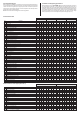
6.6 Log Menu
The menu [Log,] contains the configuration functions of the internal datalogger.
Min
Max
Standard
Unit
Description
Fun
Min
Max
Standard
Unit
F62][,
0
Datalogger operating mode
Minimum room temperature variation to force
writing data to the memory
Variation of the digital input or the outputs to
force data writing
Sampling time (time between records in the
memory)
Overwrite old records when the memory is full?
F63][,
F64][,
F65][,
F66][,
10
0(NO)
NO
NO
2
999
10
YES
YES
2
30
0(NO)
NO
YES
-
sec.
°C
-
-
0
10
NO
NO
2
999
18
YES
YES
2
30
0(NO)
NO
YES
-
sec.
°F
-
-
0(NO)
CELSIUS (°C) FAHRENHEIT (°F)
F62 - Datalogger operating mode:
It allows choosing one of the following datalogger operating modes:
[,,,0] - Always off
[,,,1] - Always on
[,,,2] - Manual operation
F63 - Sampling time (time between records in the memory):
It is the time in seconds for which the controller records samples of the temperature information, state of
the outputs, door status, and alarm status.
F64 - Minimum temperature variation to force writing data to the memory:
The temperature difference in relation to the last piece of data written in the datalogger for the data to be
recorded in the memory regardless of the sampling time set in F63. To deactivate this function, just
decrement the value until the message [,,no] is displayed.
F65 - Variation of the digital input or the outputs to force data writing:
It indicates whether changes in the digital input or in the control outputs (configured as refrigeration or
heating) will force data to be written in the memory regardless of the sampling time set in F63. The data
recording will also occur when the apparatus enters or leaves the alarm condition for OUT4 and buzzer,
and upon power failure and power restoration.
[,,no] - Off
[,yes] - On
F66 - Overwrite old records when the memory is full?:
It indicates whether the controller should start writing new data at the beginning of the datalogger
memory when the memory is full. This function prevents the last data calculated by the equipment from
being lost. If set to zero, when the datalogger memory is full the instrument and Sitrad will signal full
memory.
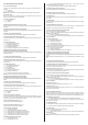
7. SIGNALS
Sensor disconnected or temperature outside specified range.
[Err,]
[EClO]
[OpEn]
[AOPn]
[AdFl]
[EMEM]
Control functions off.
Contact Full Gauge.
Reconfigure the functions values.
[OFF,]
[eCAL]
[pppp]
Invalid date and/or time (adjust the clock).
Open Door.
Open door alarm.
Datalogger memory full.
Contact Full Gauge.
AB
MT-530
super
A
A
B B
A B
A
B
A
A
B B
A B
AB
A
A
B B
A B
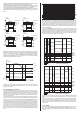
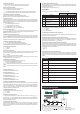
Serial Interface RS-485
Device us ed to establish th e
connection of Full Gauge Controls
instruments with Sitrad .
®
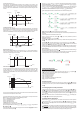
Instrument
Rede RS-485
Grounded
terminal
External
loop
®
CONV. 32 or
CONV. 256 or
TCP-485
A
A
B B
A B
**CONNECTION BLOCK FOR SERIAL COMMUNICATION
It is used to interconnect more than one instrument to the Interface. The wires must
be connected as follows: Terminal A of the instrument connected to terminal A of the
connection block, which in turn must be connected to terminal A of the Interface.
Repeat the procedure for terminals B and , with being the cable mesh (optional
ground). Terminal of the connection block must be connected to the respective
terminals of each instrument.
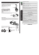
MT-530
super
Keep Sitrad up-to-date through the
site: http://www.sitrad.com.br
®
8. INTERCONNECTING CONTROLLERS, RS-485 SERIAL
INTERFACE, AND COMPUTER
*Sold Separately