
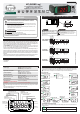
Product Overview

6.5.1 Description of the parameters
F01 - Controller's operating mode:
Configures if the controller operates in the basic mode (45 functions) or in the advanced mode (61
functions):
[,,,0] - Basic mode
[,,,1] - Advanced mode
NOTE: The features of the advanced mode will be disabled when the controller is in the basic mode.
F02 - Indication offset:
Allows for the compensation of possible deviations in the temperature reading caused by the
replacement of the sensor or changes in the cable length.
F03 - Stage 1 operating mode:
[,,,0] - Refrigeration
[,,,1] - Heating
F04 - Minimum setpoint allowed to the end user (1st stage):
Electronic backstop aimed to prevent an exceedingly low temperature being inadvertently adjusted in
the setpoint.
F05 - Maximum setpoint allowed to the end user (1st stage):
Electronic backstop aimed to prevent an exceedingly high temperature being inadvertently adjusted in
the setpoint.
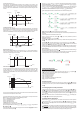
F06 - Stage 1 control differential (hysteresis):
It is the temperature difference (hysteresis) between switching output OUT1 ON and OFF.
F07 - Minimum delay to switch on stage 1 output again:
It is the minimum time the OUT1 output will remain off, i.e. the length of time between the last stop and
the next start up.
F08 - Stage 2 operating mode:
[,,,0]- Refrigeration (controlled by SP2)
[,,,1]- Heating (controlled by SP2)
[,,,2]- Refrigeration (controlled by SP1)
[,,,3]- Heating (controlled by SP1)
[,,,4]- 2nd stage of the refrigeration in rotation (controlled by SP1)
F09 - Minimum setpoint allowed for the end user (2nd stage):
F10 - Maximum setpoint allowed for the end user (2nd stage):
Electronic backstop aimed to prevent exceedingly low or high temperatures being inadvertently
adjusted in the setpoint.
F11 - Stage 2 control differential (hysteresis):
It is the temperature difference (hysteresis) between switching output OUT2 ON and OFF.
F12 - Minimum delay to switch on stage 2 output again:
It is the minimum time the OUT2 output will remain off, i.e. the length of time between the last stop and
the next start up.
F13 - Stage 3 operating mode:
[,,,0]- Refrigeration (controlled by SP3)
[,,,1]- Heating (controlled by SP3)
[,,,2]- Cyclical Timer
[,,,3]- Minimum ventilation
[,,,4]- Refrigeration (controlled by SP1)
[,,,5]- Heating (controlled by SP1)
[,,,6]- 3rd stage of the refrigeration in rotation (controlled by SP1)
NOTE: The operation of the minimum ventilation is described on item 6.3.15.
F14 - Minimum setpoint allowed to the end user (3rd stage):
F15 - Maximum setpoint allowed to the end user (3rd stage):
Electronic backstop to prevent exceedingly low or high temperatures being inadvertently adjusted in the
setpoint.
F16 - Stage 3 control differential (hysteresis):
It is the temperature difference (hysteresis) between switching output OUT3 ON and OFF.
F17 - Minimum delay to switch on stage 3 output again:
It is the minimum time the OUT3 output will remain off, i.e. the length of time between the last stop and
the next start up. Programmed only if F13=0, 1, 4, or 5.
F18 - Stage 3 cyclical timer time base:
[,,,0] - Seconds
[,,,1] - Minutes
F19 - Time to activate stage 3 cyclical timer:
This function depends on F22. Whenever the temperature reaches the value configured in [,Sp1] the
time configured in this function is observed before activating the cyclical timer. To activate the timer at
the moment [,Sp1] is reached, configure this function with 0.
F20 - Time of cyclical timer of stage 3 on ([Con,]):
Time for which the cyclical timer will remain active.
F21 - Time of cyclical timer of stage 3 off ([Coff]):
Time for which the cyclical timer will remain inactive.
F22 - Cyclical timer operating mode:
[,,,0] - Independent cyclical timer
[,,,1] - Cyclical timer triggered by the stage 1 setpoint (SP1)
[,,,2] - Stage 1 linked to the cyclical timer (timer on upon power up)
[,,,3] - Stage 1 linked to the cyclical timer (timer off upon power up)
[,,,4] - Cyclical timer output is on whenever stage 1 output is on
[,,,5] - Cyclical timer output cycles whenever stage 1 output is on
F23 - Audible alarm (buzzer) operating mode:
[,,,0] - In-range alarm (F24 e F25)
[,,,1] - Out-range alarm (F24 e F25)
[,,,2] - Out-of-range alarm related to the stage 1 setpoint ([SP1,] - F24 and [SP1,]+F25), the
absolute values of F24 and F25 are considered.
[,,,3] - Rotation mode alarm (goes off when more than one output is activated).
F24 - Buzzer operating point (lower threshold):
It is the lower temperature value for the buzzer alarm to activate according to F23.
F25 - Buzzer operating point (upper threshold):
It is the higher temperature value for the buzzer alarm to activate according to F23.
F26 - Buzzer on time:
It is the time the buzzer will remain on (active cycle). To disable the audible alarm (buzzer), configure this
function with 0.
F27 - Buzzer off time:
It is the time the buzzer will remain off (inactive cycle). To disable the audible alarm (buzzer), configure
this function with 0.
F28 - Alarm inhibition time upon power up:
It is the time for which the buzzer will remain off, even in alarm conditions, for a certain period after
initialization, since the system has not yet reached the working temperature.
F29 - Time to reactivate the buzzer when manually inhibited:
This function allows for three different configurations:
[Auto]- The buzzer will be inhibited until the temperature reaches the normal working condition and
returns to the alarm condition again.
[,,,0] - Buzzer cannot be inhibited by the easy access keys.
[,,,1] to [,999] - Buzzer will be inhibited during this period (in minutes), switching on again if the
alarm condition persists.
F30 - Stage 4 operating mode:
[,,,0] - Refrigeration (controlled by SP4)
[,,,1] - Heating (controlled by SP4)
[,,,2] - In-range alarm (F31 and F32)
[,,,3] - Out-of-range alarm (F31 and F32)
[,,,4] - Out-of-range alarm related to the stage 1 setpoint ([,SP1] - F31 and [,SP1] + F32), the
absolute values of F24 and F25 are considered.
[,,,5] - Refrigeration (controlled by SP1)
[,,,6] - Heating (controlled by SP1)
[,,,7] - 4th stage of the refrigeration in rotation (controlled by SP1)
F31 - Minimum setpoint allowed to the end user (4th stage):
F32 - Maximum setpoint allowed to the end user (4th stage):
Electronic backstop to prevent exceedingly low or high temperatures being inadvertently adjusted in the
setpoint.
NOTE: When stage 4 is defined as alarm (F30=2, 3, or 4), the activation points are defined in F31 and
F32.
F33 - Stage 4 control differential (hysteresis):
It is the temperature difference (hysteresis) between switching output OUT4 ON and OFF.
F34 - Minimum delay to switch on stage 4 output again:
It is the minimum time the OUT4 output will remain off, i.e. the length of time between the last stop and
the next start up. Programmed only if F30=0, 1, 5, or 6.
F35 - Alarm inhibition time upon power up:
This function serves to inhibit the alarm for a certain period after the start up, because the system has
not yet reached the working temperature (only if F30=2, 3 or 4).
F36 - Time to reactivate the alarm when manually inhibited:
This function allows for three different configurations (only if F30=2, 3, or 4):
[Auto] - The alarm will be inhibited until the temperature reaches the normal working condition and
returns to the alarm condition again.
[,,,0] - Alarm cannot be inhibited by the easy access keys.
[,,,1] to [,999] - Alarm will be inhibited during this period (in minutes), switching on again if the
alarm condition persists.
F37 - Alarm on time ([Ton,]):
To adjust the time output OUT4 will remain active (only if F30=2, 3, or 4).
F38 - Alarm off time ([ToFF]):
To adjust the time output OUT4 will remain inactive (only if F30=2, 3, or 4). To always keep the alarm
active configure this function with 0.
F39 -Time to inhibit the alarms (delay):
When this configuration is active, the temperature must remain in the alarm condition for the defined
inhibit time before the alarm is indicated. This allows avoiding warnings originating from punctual
temperature variations. This configuration is used in the alarm output and in the audible alarm (buzzer).
F40 - Digital filter operating mode:
[,,,0]- The filter operates both on the ascending and descending slope of the temperature.
[,,,1]- The filter operates only on the ascending slope of the temperature. When the temperature
falls the response is immediate.
F41 - Digital filter intensity:
The value adjusted in this function represents the time (in seconds) for the temperature to change by
0.1° C. This function can be switched off by setting it at the minimum value 0.
F42 - Functions lock:
It allows and configures the functions lock (see item 6.3.6).
[,,,0] - Do not allow the functions lock.
[,,,1] - Allow a partial lock where the control functions will be locked but the adjustment of the
setpoint is allowed.
[,,,2] - Allow full locking.
NOTE: The view of the minimum and maximum temperature records will always be allowed.