
Product Overview

6.3.16 - Refrigeration in rotation
The rotation mode switches the output used for refrigeration, making each machine work during a
certain time and therefore makes all of them accumulate the same working time. It also enables a logic
of stages that activates the outputs simultaneously when the setpoint is not reached in normal operation
(1st stage). However, as the outputs alternate in the rotation, there is not a link between the order of
stages and outputs. Thus, when entering the second stage one more output is activated, which can be
OUT1, OUT2, OUT3 and OUT4.
To use the “Rotation” function, F46 (Stage control mode) must be adjusted to indicate the outputs that
will activate. To enable the rotation, the operating mode of the 2nd stage (F08) is automatically forced to
the rotation function. The same happens with the mode of operation of the 3rd stage if the rotation uses
the three outputs (F46 = 2). If the controller is configured to use rotation in all four stages (F46=3), the
operating mode of stage 4 (F30) is automatically forced into the rotation function. In normal operation,
when the temperature exceeds the control differential of the 1st stage, the output with less working time
(OUT1, OUT2, OUT3 or OUT4) is activated to engage refrigeration. The time it remains switched on to
reach the setpoint is accumulated. When the accumulated value of the on time of the output exceeds a
given number of hours, it gives way to the next output. This time during which the rotation will be
performed is configured in hours in function F47 (time for rotation operation), the setpoint is set in the
quick access menu (SP1) or in the function F53, and the control differential of the 1st stage is adjusted
in F06.
SP1+F33
SP1+F16
SP1+F11
SP1+F06
SP1
OUT4
OUT3
OUT2
OUT1
F48
Activation of a new output for
exceeding the control differential
Ton
Temp
OUT4
OUT3
OUT2
OUT1
SP1+F16
SP1+F11
SP1+F06
SP1
Temp.
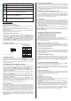
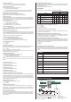
When due to any failure the active output cannot reach the setpoint, the 2nd, 3rd and 4th stages act as
backup. Two criteria are used to determine this operation for each stage, temperature differential and
time. In the first case, new control outputs will be activated as the temperature deviates from the setpoint
and exceeds the control differentials of each stage. In this way, all outputs may work together. The
differentials to include a new output are defined in relation to the setpoint (SP1) and configured in F11,
control differential of the 2nd stage, and in F16, control differential of the 3rd stage, and in F33, control
differential of the 4th stage.
For the 2nd, 3rd and 4th stages to act by time, the time is counted from the activation of the current
output of the 1st stage. If that time exceeds a certain limit (F48) without reaching the setpoint, the 2nd
stage activates the output with less accumulated time. The time count is restarted and if that limit is
exceeded again without reaching the setpoint, stage 3 activates the next output with less accumulated
time and restarts the time count. If this given limit is exceeded again, the remaining output is activated.
The time to activate a new output is configured in minutes in F48.
Activation of a new output for exceeding the
maximum time to reach the setpoint
Ton
Temp
SP1+F33
SP1+F16
SP1+F11
SP1+F06
SP1
OUT4
OUT3
OUT2
OUT1
F48
Temperature [°C]
Setpoint
Cooling
Setpoint + Histerese
Time [S]
Temperature [°C]
Cooling
Cyclical
timer
OUT1
Figure 3
Setpoint - Histerese
Setpoint
Setpoint + Histerese
Time [S]
Cyclical
timer
OUT1
Figure 4
Setpoint - Histerese
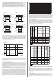
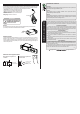
- Stage 1 linked to the cyclical timer (timer off upon power up) (F22=3): The operation is similar to
the previous configuration. The difference in this configuration is that the timer starts off.
- Cyclical timer output is on whenever stage 1 output is on (F22=4): in this operating mode timer
cycles according to the times configured in F20 ([COn]) and F21 ([COff]), and stage 3 stops cycling
and keeps the output switched on, whenever stage 1 output switches on, as shown in Figure 3.
- Cyclical timer output cycles whenever stage 1 output is on (F22=5): stage 3 will cycle only when
stage 1 output is on, observing the times configured in F20 ([COn,]) and F21 ([COff]), as shown in
Figure 4.
Temperature [°C]
Cooling
Setpoint
Setpoint + Histerese
Time [S]
Cyclical
timer
OUT1
Setpoint - Histerese
Figure 1
Temperature [°C]
Cooling
Setpoint
Setpoint + Histerese
Time [S]
Cyclical
timer
OUT1
Setpoint - Histerese
Figure 2
Figure 5
SP1 + F16
Temperature
SP1
SP1 - F06
OUT1
Ventilation
Temperature [°C]
Heating
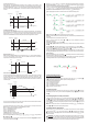
Stage 3 configured as minimum ventilation; it will act together with stage 1 (configured for heating) in
systems that require minimum ventilation. Functioning as follows: when the temperature is between
SP1 and SP1-F06 or between SP1 and SP1+F16, stage 3 will cycle according to the times configured in
F20 ([COn,]) and F21 ([Coff]). If the temperature is below SP1-F06, the ventilation is switched off,
and if the temperature is higher than SP1+F16, the ventilation remains on, and stays in this condition
until it reaches the setpoint again, as shown in Figure 5.
Like in the previous stages, stage 4 can also be configured as refrigeration or heating. It can also act as
an in-range, out-of-range, and relative out-of-range alarm (F30 = 2, 3, and 4). All stages can operate as
refrigeration in rotation mode.
The buzzer may be activated when more than one output is activated simultaneously (2nd, 3rd and 4th
stages). To do this, F23 (buzzer operation mode) must be defined as 3 - Error alarm in the rotation
mode.
Also related to protection routines, it is possible to set the minimum time between the stage switch off
the output and switch it on again, configured in F07, F12, F17 and F34, minimum delay to switch on
again the outputs of the 1st, 2nd, 3rd and 4th stages respectively. There is also a logic to prevent the
outputs from switching on at the same time by forcing a time interval between activations, which is
configured in F49.
6.3.17 - HACCP
This controller helps food industry management systems by allowing monitoring of the critical control
points required by HACCP (Hazard Analysis and Critical Control Points) regulations. Up to 24
records of the following types are maintained: high temperature, low temperature, digital input, and
power failure.