
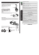
Product Overview
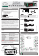

Hold down for 2 seconds: Inhibits the audible alarm and alarm output.
Quick touch: Maximum and minimum temperature display.
<
<
<
Hold down for 2 seconds: clear history when records are being displayed.
Held down simultaneously: enter the function menu.
<
<
<
Quick touch: If working in rotation mode, displays the operating time
of the refrigeration outputs.
Hold down for 2 seconds: HACCP menu.
;
/
Hold down for 10 seconds: manual datalogger activation.
<
<
6.3 Basic operations
6.3.1 Operation mode
This controller operates in two different modes:
Basic mode: it has 45 functions and datalogger features.
Advanced mode: has 61 functions, 1 datalogger, digital input, hourmeter, HACCP, and rotation control
mode.
To select the controller's operating mode, access function F01 on menu [Func].
NOTE: The features of the advanced mode will be disabled when the controller is configured to operate
in the basic mode (F01=0).
NOTE 2: The features described in items 6.3.9, 6.3.16 and 6.3.17 will only be available when the
controller is configured to operate in advanced mode (F01=1).
6.3.2 Selection of the type of sensor
It is required when you want to change the type of sensor connected to the controller. You can choose
the NTC thermistor, PT100* or Pt1000*. To define the type of sensor, press <and> simultaneously
(quick touch) when the temperature is being displayed, enter the option [Code] using the access code
[,312] and then press/. The message [Sens], will be displayed, then select the desired sensor
type[,ntc] (thermistor NTC) or [pt01](thermistor PT100*) or [pt10](thermistor Pt1000*)
using the <or>, keys, and press/to confirm. Whenever the type of sensor is changed, the
configuration of the functions assumes the factory default, so they need to be configured again.
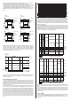
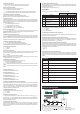
6.3.3 Sensor Connection
The NTC, PT100*, or PT1000* sensors must be connected according to the picture below:
6.3.4 Selection of units
To select the units the system will use to operate, press <and> simultaneously while the
temperature is being displayed, enter the option [Code] using the access code [,231] and then
press/. Then select the desired unit [,=C,] or [,=F,] using the<or>key, and press/to
confirm. Whenever the units are changed, the functions' configuration assumes the factory default, so
they need to be configured again.
6.3.5 Adjusting the desired temperature (Setpoint)
To enter the setpoint adjustment menu, press / for 2 seconds until [Set,]is displayed or use the
quick access menu key. The message [Sp1,] and then the value to adjust the setpoint of stage 1 will
be displayed in sequence. Use the< or >keys to change the value and press /to confirm.
- If stage 2 is configured to operate as refrigeration controlled by SP2 (F08=0) or heating controlled by
SP2 (F08=1), the message [Sp2,] will be displayed afterwards. Use the< or >keys again to
change the value and press/to confirm.
- If stage 3 is configured to operate as refrigeration controlled by SP3 (F13=0) or heating controlled by
SP3 (F13=1), the message[SP3,]will be displayed afterwards. Use the< or >keys again to
change the value and press /to confirm.
- If stage 4 is configured to operate as refrigeration controlled by SP4 (F30=0) or heating controlled by
SP4 (F30=1), the message[SP4,]will be displayed afterwards. Use the< or >keys again to
change the value and press /to confirm.
If the 3rd stage is configured as a cyclical timer (F13 = 2) or minimum ventilation (F13 = 3), the
adjustment of the time of the cyclical timer of the 3rd stage on ([Con,])and the time of the cyclical
timer of the 3rd stage off ([Coff]). will be possible. The adjustment of alarm on ([ton,]) and off
([toff]) times will be allowed if stage 4 is configured as alarm (F30 = 2, 3, or 4).
Finally, the message [----]indicates that the configuration is complete.
6.3.6 Functions lock
The use of the lock function brings greater security to the operation of the instrument. The setpoint and
other parameters can be visible to the user when active, but they are protected against undue changes
(F42=2) or only block changes to the control functions and leave the adjustment of the setpoint enabled
(F42=1). To activate the functions lock, access [LOC,] in the quick access menu. The message
[no,,](lock must be enabled and deactivated) will be displayed. When the message is being
displayed, press and hold > for the time configured in (F43) for the functions to be locked. The
activation will be indicated by the message [LOC,][On,,]. To enable the use of this function, F42
must be configured with 1 or 2. The message [LOC,] that is displayed when trying to change any
parameter indicates that functions lock is active. To deactivate it, switch the controller off and on again
with the>key held down. Keep the key held down until the [LOC,][OFF,] message indicates the
unlocking (10 seconds).
6.3.7 Control functions shutdown
Turning the control functions off allows for the controller to operate just as an indicator of temperature,
keeping the control outputs and the alarms disconnected. Use of this feature is enabled or disabled by
the control functions shutdown (F44) function. When enabled, the control and alarms functions are
turned off ([CTRL][OFF,]) or on ([CTRL][ON,,]) through the quick access menu in the option
[CTRL]. When the control functions are off the message [OFF,]will then be displayed alternately
with the temperature and the other messages.
6.3.8 Minimum and maximum temperature record
The display of minimum and maximum temperature records can be checked through the quick access
menu or by pressing the<key. The minimum and maximum temperatures recorded will be displayed
in sequence. To erase the minimum and maximum values recorded, keep the < key pressed for 2
seconds while the records are being displayed or use the option [Creg] in the quick access menu.
The message [rset] indicates that the records were erased.
6.3.9 Hourmeter
The hourmeter indicates the number of working hours for the outputs configured as heating /
refrigeration. The hourmeter can be viewed through the quick access menu (;) in the option [Hour]
and the working time of each output is displayed in hours. The maximum working time of the output for
maintenance purposes can be configured through function F57. When the compressor's number of
working hours reaches the value configured in this function an alert will be displayed [Man1] for output
1, [Man2] for output 2, [Man3] for output 3 or [Man4] for output 4, indicating that maintenance is
due for the corresponding output.
To disable the alert or reset the hourmeter counter, access option [rHou] in the quick access menu
(;), sing the<or>keys to select the hourmeter to reset([Out1] ,[Out2],[Out3]or[Out4])
and then press /. The message [rst1], [rst2], [rst3]or [rst4]will be displayed
depending on the output chosen.
6.3.10 Operation time of the outputs in rotation mode
Pressing the > key in the rotation (F46=1, 2 or 3) mode the following will be shown:
[,tt1]and then the total accumulated time in hours for OUT1
[,tt2]and then the total accumulated time in hours for OUT2
[,tt3]and then the total accumulated time in hours for OUT3
[,tt4]and then the total accumulated time in hours for OUT4
Then the message [,AT1], [,AT2], [,AT3] or [,At4] will be displayed depending on the
current active output, and then the time remaining for the output change will be displayed.
NOTE: The total time of OUT3 [,tt3] will only be displayed if F46=2 or 3 and the total time of OUT4
[,tt4] will only be displayed if F46=3.
Resetting of the time for rotation and selection of the current output:
If the > key is pressed and kept held down while the time is being displayed, the times are reset at the
end of the display. Once this is done, the message [rset] will be displayed and then [Out1],
[Out2], [Out3] or [Out4], indicating which output will be the first to be activated. Every time the
times are reset, the action goes to the next output.
6.3.11 View current date and time
Quickly pressing the/key (quick touch) makes it possible to view the current date and time set in the
controller. The current day ([,--d]), mouth ([,--m]), year ([,--y]), hour and minute ([00:00]).
will be shown in sequence on the display. It is also possible to view the date and time through the quick
access menu in the option [CLO,].
6.3.12 Manual datalogger activation
The manual activation of the internal record of temperature values and state of outputs (Datalogger) is
performed through the quick access menu in the option [dtl,]. The message [dtl,] will be
displayed followed by the message [On,,] when the datalogger is activated or [OFF,] when it is
deactivated. It is also possible to activate the datalogger manually by pressing the < and > keys for
10 seconds.
1
5
6
7
8
2
3
4
NTC
PT100*
PT1000*
*This sensor is sold separately.
Table of wire gauge / max distance
for the two wire PT100*.
Diameter Máx. dist.
(AWG) (mm) (meters)
14
16
18
20
22
24
26
1.63
1.29
1.02
0.81
0.64
0.51
0.40
18.1
11.4
7.2
3.0
1.9
1.8
1.1
6.3.13 Audible alarm and alarm output inhibitor
To inhibit the alarm output OUT4 and / or the audible alarm (buzzer), when they are active, press > for
2 seconds. In this case, if OUT4 and buzzer are active, they will both be inhibited.
It is also possible to inhibit the alarm or buzzer through the option [inib] in the quick access menu
;, where it is possible to choose the individual alarm to be inhibited ([Out4] or [bu22]) using the
< or > keys and pressing /.
6.3.14 Power failure alarm
Output OUT5 can be used as power failure alarm and / or alert. During the normal operation of the
controller this output will remain deactivated and during a power failure it is activated and remains active
until the power is restored and the controller resumes normal operation.
6.3.15 Stages
controller has four stages.
Stages 1 and 2 work only as refrigeration or heating.
Besides operating as refrigeration or heating, Stage 3 can act as a cyclical timer or minimum ventilation.
It has five operating modes when configured as cyclical timer:
- Independent (F22=0): the timer cycles are according to the times configured in F20 ([COn,]) and
F21 ([COff]).
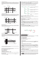
- Timer triggered by SP1 (F22=1): the timer is triggered whenever the temperature reaches the value
configured for SP1. The timer switches off when the temperature reaches SP1 + F06 (if stage 1 is
configured as refrigeration) or SP1 - F06 (if stage 1 is configured as heating), as shown in Figure 1.
- Stage 1 linked to the cyclical timer (timer switches on upon power up) (F22=2): in this
configuration, the timer cycles according to the times configured in F20 ([COn,]) and F21 ([COff]) .
The Stage 1 starts to cycle when the temperature reaches SP1 + F06 (if stage 1 is configured as
refrigeration) or SP1 - F06 (if stage 1 is configured as heating), as shown in Figure 1.
MT-543e Log