
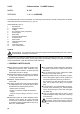
Technical data
54
L Place the machine on the horizontal surface pre-
YLRXVO\SUHSDUHG
%HIRUHFRQQHFWLQJWKRURXJKO\ZDVKWKHPDLQVZDWHU
pipes:
L/HDYHWKHZDWHUVXSSO\WDSVUXQQLQJDWIXOOSUHV-
sure for several minutes.
L&RQQHFWWRWKHPDLQVZDWHUVXSSO\
L Connect the machine to the socket.
7KRURXJKO\ZDVKDOOWKHZDWHUSLSHVRIWKHPDFKL-
ne:
L/HDYHWKHZDWHUVXSSO\WDSVUXQQLQJDWIXOOSUHV-
sure.
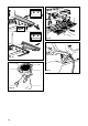
L Switch on main switch 1 (Fig.7): wait until the boiler
¿OOVXSWRWKHOHYHOVHW
L Switch on boiler resistance switch 2 (Fig.7) to begin
heating the water in the boiler.
L Operate each unit in order to allow the water to
HVFDSHIRUDERXWRQHPLQXWHUHSHDWWKHRSHUDWLRQ
twice.
L Deliver steam from the steam jets for about one
minute.
L'HOLYHUKRWZDWHUIRUDERXWRQHPLQXWHUHSHDWWKH
operation twice.
L Switch off switches 1 and 2.
L(PSW\ WKH ZDWHU IURP WKH ERLOHU VHH SRLQW
10.3.1.
IMPORTANT
6KRXOGWKHPDFKLQHQRWGHOLYHUZDWHUIRURYHU
KRXUVZDVKWKHLQWHUQDOFRPSRQHQWVEH-
IRUHEHJLQQLQJZRUNUHSHDWLQJWKHRSHUDWLRQV
DVGHVFULEHGDERYH
6.1. Connections to be made by the
user
+RRNXS PXVW EH FDUULHG RXW E\ TXDOL¿HG
SHUVRQQHO LQ IXOO DFFRUGDQFH ZLWK IHGHUDO
VWDWHDQGORFDOUHJXODWLRQV
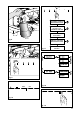
6.1.1. Water supply (Fig.5)
This equipment is to be installed to
comply with the applicable federal, state
or local plumbing codes.
Connections must be installed close to the machine.
L Water drainage pipe 1, having a minimum internal
diameter of 30 mm, equipped with a water-trap
accessible for inspection.
L:DWHUVXSSO\SLSHZLWKD*FXWRIIWDS
0DNHVXUHWKDWWKHPD[LPXPVXSSO\SUHVVXUH
GRHVQRWH[FHHGEDURWKHUZLVHLQVWDOOD
SUHVVXUHUHGXFHU
6.1.2. Electric supply (Fig.5)
7KHPDFKLQHLVVXSSOLHGUHDG\IRUFRQQHFWLRQ
DFFRUGLQJWRWKHUHTXLUHGHOHFWULFDOVSHFL¿FDWLRQV
Before connecting the machine ensure that the plate
GHWDLOVFRPSO\ZLWKWKRVHRIWKHHOHFWULFGLVWULEXWLRQ
network.
7KH HOHFWULFDO FRQQHFWLRQ FDEOH PXVW EH GLUHFWO\
connected to the connection provided according to
FXUUHQWOHJLVODWLRQ(QVXUHWKDWWKHHDUWKLQJV\VWHP
LVHI¿FLHQWDQGLQFRPSOLDQFHZLWKFXUUHQWOHJDOUH-
quirements.
7KHHDUWKLQJ V\VWHPDQG WKH OLJKWHQLQJ SURWHFWLRQ
V\VWHP PXVW EH UHDOL]HG LQ DFFRUGDQFH ZLWK WKH
provisions of current legislation.
)RUWKHVXSSO\QHWZRUNXVHDFDEOHLQFRPSOLDQFHZLWK
standards with protective conductor (earthing wire).
For three-phase power use a cable with 3 conductors
( 3 phases + neutral + earth).
)RUVLQJOHSKDVHSRZHUVXSSO\XVHDFDEOHZLWK
conductors (phase + neutral + earth).
,QERWKFDVHVLWLVQHFHVVDU\WRSURYLGHDQDXWRPDWLF
differential switch 4 (Fig. 5) at the start of the power
cable, complete with magnetic release elements in
DFFRUGDQFHZLWKWKHLGHQWL¿FDWLRQSODWHGHWDLOV)LJ
1). The contacts must have an opening of equal or
over 3 mm and with dispersed current protection of
30 mA.
5HPHPEHUWKDWHDFKPDFKLQHPXVWEH¿WWHGZLWKLWV
RZQVDIHW\HOHPHQWV
WARNING:
6KRXOGWKHSRZHUVXSSO\FDEOHEHGDPDJHG
LWLVWREHUHSODFHGE\WKHPDQXIDFWXUHURUE\
LWVWHFKQLFDODVVLVWDQFHVHUYLFHRUE\SHUVRQ
ZLWKHTXLYDOHQWTXDOL¿FDWLRQLQRUGHUWRSUH-
YHQWDQ\ULVNV
6.2. Preliminary operations (Fig.6)
P O T E N T I A L - E Q U A L I Z I N G
CONNECTION
7KLVFRQQHFWLRQZKLFKLVWKHRQHFDOOHGIRUE\VHYHUDO
norms, avoids electrical potential differences, building
XSEHWZHHQDQ\HTXLSPHQWWKDWPD\EHLQVWDOOHGLQ
the same room. There is a terminal clip on the under
side of the base of the machine to which an external
potential-equalizing wire should be connected.
This connection is ABSOLUTELY NECESSARY and
must be made right after the machine is installed.
Use a wire whose cross-sectional area conforms to
the existing norms.
6.3. Connections