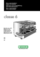
Uso e manutenzione Emploi et entretien Gebrauch und Instandhaltung Use and maintenance Uso y manutención Uso e manutenção classe 6 Macchina per caffè Machine à café Kaffeemaschinen Coffee machine Máquina para café Máquina para café ●E ●S ●L
IT FR DE EN ES PT Gentile cliente, grazie per averci accordato la Sua fiducia. Siamo sicuri che il prodotto che Lei ha acquistato risponderà in pieno alle Sue aspettative, come tutti gli altri articoli della produzione RANCILIO. Il prodotto che Lei si accinge ad usare è il risultato di approfonditi studi e meticolose sperimentazioni fatte dalla RANCILIO per offrirLe quanto di più funzionale, sicuro ed apprezzabile, anche sotto il profilo del design, si possa trovare sul mercato.
EUROPEAN UNION ONLY Trattamento dei rifiuti delle apparecchiature elettriche ed elettroniche. Smaltire il prodotto seguendo le norme vigenti relative allo smaltimento differenziato presso centri di raccolta dedicati. Non trattare come semplice rifiuto urbano. Per qualsiasi informazione necessaria contattare il costruttore all’indirizzo indicato nel libretto istruzioni.
20010 Villastanza di Parabiago (MI) Viale della Repubblica 40 DICHIARAZIONE DI CONFORMITA’ CE - DECLARATION DE CONFORMITE CE EG-KONFORMITÄTSERKLÄRUNG - EC DECLARATION OF CONFORMITY DECLARACIÓN DE CONFORMIDAD CE - DECLARAÇÃO DE CONFORMIDADE CE Noi RANCILIO Macchine per caffè S.p.A.
Descrizione attrezzatura a pressione-Description de l’appareillage sous pression-Beschreibung der unter Druck stehenden GerätePressure device description-Descripción de los equipos de presión - Descrição dos equipamentos de pressão Pressione Max.r Pression - Druck Pressure - Presión Pressão Caldaia - Chaudière Kessel - Boiler Caldera - Caldeira 0,18/1,8 Mpa/bar Pressione Max. Pression - Druck Pressure - Presión Pressão Scambiatore - Echangeur Austauscher - Exchanger Intercambiador - Intercambiador 1.
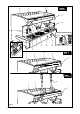
3 6 4 15 1 2 9 17 13 10 1 11 5 12 2 8 4 1 14 3 6 1 7 1 4 16 1 Fig.
3 H A C B ota 1 (Ø 30 mm) vo LL 4 D 2 (3/8"G) Fig. 4 Fig. 5 Fig. 6 Fig.
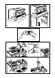
A 11 B C E D MOD. E 4B 5B 6 10 3 2 1 8 11 9 4A 5A MOD. S 6 7 4C 11 MOD. L 5C 7 Fig.
Fig. 9 Fig. 10 Fig. 12 1 Fig. 11 2 3 1 2 4 Fig. 13 3 5 4 Fig.
IT ITALIANO 12-23 FR FRANCAIS 24-35 DE DEUTSCH 36-47 EN ENGLISH 48-59 ES ESPAÑOL 60-71 PT PORTUGUÊS 72-83 SCHEMI ELETTRICI SCHEMAS ELECTRIQUES SCHALTPLANE WIRING DIAGRAMS ESQUEMAS ELECTRICOS ESQUEMAS ELÉTRICOS SCHEMI IDRAULICI SCHÉMAS HYDRAULIQUES HYDRAULIKPLÄNE HYDRAULIC DIAGRAMS ESQUEMAS HIDRÁULICOS ESQUEMAS HIDRÁULICOS EN 84-90 91-93 The operations marked with this symbol are to be undertaken exclusively by an installation technician The operations marked with this symbol are to b
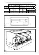
NAME: Coffee machine, CLASSE 6 series MODEL: E -S - L VERSIONS: 1 - 2 - 3 - 4 GROUPS (L) 2 - 2 COMPACT - 3 GROUPS (E - S) The label illustrated on the EC Declaration of Conformity of this instruction manual corresponds to the identification label placed on the machine Fig. 2. (Pos. A). Label identification (Fig.
2. DESCRIPTION The machines in the CLASSE 6 series have been designed to prepare express coffee and hot beverages. A positive-displacement pump inside the machine powers the heater in which the water is heated. By pressing the appropriate buttons, water is supplied to the spouts in the form of hot water or steam, according to needs. The hot water used to make drinks comes from the boiler and is mixed directly with cold water from the water outlet.
2.3. Mechanical protective devices 2.4. Electric safety devices The machine is equipped with the following protective devices: The safety devices provided are: ● 12V low tension push buttons an the E control key panel; ● thermal protection on the pump motor; ● gas failure thermocouple and thermocouple thermostat automatically closing gas tap; ● safe resistance thermal; ● Electronic safety devices.
The operator must always follow the indications contained in this manual. In the case of a failure or if the machine is not working properly, switch it off and do not attempt any direct repair. Refer exclusively to a service centre.
6.1. Connections to be made by the user Hook-up must be carried out by qualified personnel in full accordance with federal, state and local regulations. 6.1.1. Water and gas supply (Fig.5) This equipment is to be installed to comply with the applicable federal, state or local plumbing codes. Connections must be installed close to the machine. ● Water drainage pipe 1, having a minimum internal diameter of 30 mm, equipped with a water-trap accessible for inspection.
If you press the button for 2 seconds, dispensing is continuous and only stops when the button is pressed again. Dispensing is discontinued automatically after 30 and 60 seconds, respectively. 7. OPERATION 7.1. Controls (Fig.8) 1 Main switch Two-position switch with led. Turn on the switch (led on) the machine is turned (apart from the boiler) and the pump is turned on to fill the boiler; 2 Boiler resistance switch Two-position switch with led.
Models with gas (Fig.8) ● Turn on the water supply tap 2 (Fig.5). ● Turn on the gas tap 3 (Fig.5). ● Turn the main switch 1; the pump is activated, filling the boiler. ● When the correct level is reached, the pump stops. Turn the switch 2 in order to activate the resistance in boiler.
8.3. Heating a beverage ● Immerse the steam spout into the liquid to be heated. ● Gradually turn on the steam tap 6 (Fig.8); the steam that bursts in the liquid heats it to the desired temperature. ● Turn off the steam tap when the desired temperature has been reached. Immediately after carrying out this operation, clean the spout with a sponge or clean cloth. Be careful as the spout is hot and may burn your hand. 8.4. Preparing tea, camomile, etc.
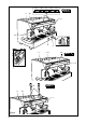
9.1.2. Adjusting the quantity of hot water Proceed as follows: 1 Press the continuous E button on any button panel and hold down for 8-10 seconds until water stops flowing from the dispensing unit and the led of the E button on the first button panel on the left starts flishing. The machine is ready to accept quantity variations. 2 Put a cup or a jug to receive the water under the water spout 16 (Fig.3). 3 Push the delivery button 5B 4 Once the required amount is reached, press the button 5B again.
Cleaning the filters and delivery heads (Fig.12) Operation to be carried out when the machine is off and cold. ● Prepare a solution of 4 sachets of detergent powder Code 69000124 dissolved in a litre of boiling water in a stainless steel, plastic or glass recipient (NOT ALUMINIUM OR IRON). ● Remove the filters and immerse them with the filter holders in the prepared solution, leaving them for at least 10/20 minutes (all night is better).
13. MACHINES WITH ALTERNATIVE GAS HEATER VERSION (Fig.14) N.B. Installation of the machine and any adjustment or adaptation to the type of gas should be done by a technically qualified person. The machine leaves the factory all set for use with liquid gas (GPL). The gas regulator (1) is therefore fitted with the appropriate injector shown in the table below: Nominal thermic capacity GPL G30 - 29 mbar Natural gas G20 - 20 mbar (cent of milimeter) (cent of milimeter) 2 Gr. 2,5 KW (2150 Kcal/h.