WES Installation and Operation Manual 3 3 Page 1 WES3 Installation and Operations Manual V1.
Contents System Units Unit Diagrams WES3 Units Emergency Call Point Heat Sensor Smoke Sensor Emergency Control Unit Link Interface Basic System Setup Health and Safety Manual Handling, Storage and Transportation Service and Maintenance Damaged Units Installation Procedure System Operation Raising the Alarm Manual Activation Automatic Activation Silencing the Alarm Resetting a Call Point Raising a Medical Alert Cancelling a Medical Alert LED Indications Unit Alive Indication Amber LED Indication Red LED Indi
System Logs Settings Change Access Code Unit Numbering Unit Numbering LED Indications Date and Time Backlight Mobile Base Interface Radio Equipment Statement Emergency Call Point Technical Data Emergency Control Unit Technical Data Heat Sensor Technical Data Smoke Sensor Technical Data Link Technical Data Interface Technical Data Heat Sensor Maintenance Routine Inspection Operational Test Function Test Cleaning Smoke Sensor Maintenance Routine Inspection Operational Test Function Test Cleaning Contact Us P
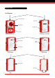
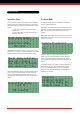
System Units Unit Diagrams Antenna Sounder and Strobe LCD Display LED Indicators Navigation Pad Call Point Emergency Call Point Emergency Control Unit Antenna Heat Dectector Smoke Sensor LED Indicators Sensor Units Sensor Units Antenna LED Indicators Cable Gland Link Page 4 Interface WES3 Installation and Operations Manual V1.
System Units WES3 Units Smoke Sensors All WES3 units have three indicator LEDs, plus two push buttons, labelled A and B. WES3 Smoke Sensors are silent but communicate with sounding units automatically to raise the alarm if smoke is detected. There are two Smoke Sensors in the WES3 range; a Standard Smoke Sensor and a Dust Resistant Smoke Sensor. Units should be securely fixed using the two integrated mounting points.
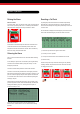
Basic System Setup A basic system is made up of a minimum of three WES3 units, at least one being a WES3 Emergency Control Unit. Emergency Call Points are essential to all systems if an audible evacuation alarm is required. Health and Safety As with all site practices, working safely must be a priority when installing the WES3 system.
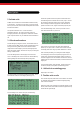
Basic System Inspection Delay Pre Alarm Mode The Inspection Delay setting allows an optional delay period between triggering a unit and the site wide alarm being raised. This can allow time for the incident to be validated on site, and a decision to be made to either i) confirm alarm is genuine, raise site wide alarm and evacuate site, or ii) confirm false activation, cancel the alarm and return to normal (non-alarm) state.
Basic System 2. Activate units All WES3 units are delivered to site with batteries installed and ready for site activation. To activate a unit, hold down ‘A’ and press ‘B’ three times in quick succession. All three LEDs will briefly illuminate and then the amber LED will flash. This operation activates the unit – no radio connection is established at this point. The system must include a least one Emergency Call Point in order to generate an audible alarm.
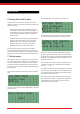
Basic System 6. Securely fix the units in place Each WES3 unit must be securely fixed in place to ensure correct operation. The tamper switch on the rear of the unit must be in contact with the wall or ceiling. • Sensor units are ceiling mounted and intended for indoor use only. Installation of sensors may involve working at height or on elevated platforms. Ensure a risk assessment has been carried out and all reasonable safety precautions are in place before commencing work.
System Operation Raising the Alarm Resetting a Call Point Manual activation To raise the alarm, press any call point in the system. The call point will latch into the pressed position and a mechanical yellow and black striped flag will be displayed in the call point window as below. Any Emergency Call Point that has been activated will periodically beep after the re-arm period has ended as a reminder that the unit needs to be mechanically reset using the key before they can be used to raise a alarm.
System Operation Raising a Medical Alert The medical alert can be raised from any Emergency Call Point by pressing and holding the B button for 2 seconds, until the alternating amber-green LEDs flash repeatedly. WES3 can receive and display multiple Medical Alerts on the Emergency Control Unit, and these can be managed and cancelled individually. Multiple medical alerts are displayed in chronological order, and prioritised over other system messages except fire alarm.
System Tests Initiating a System Test System Integrity Test (Polling) The System Test is started from the Emergency Control Unit Settings Menu: WES3 includes a System Integrity Test that can report on changes to the network configuration, such as when additional or unexpected units are detected on the network, or when units have been removed. Select WES MAIN MENU System Logs Settings 1. The access code is required to access the Settings Menu. The default PIN number is 1234.
Moving a Unit on Site After moving a unit, we recommend that you conduct a system test to check that the movement has not adversely affected radio communication. Ensure any site fire plans are updated with any revisions to WES3 unit numbering and location.
Advanced Emergency Control Unit Operation One or more Emergency Control Units can be added to a basic system to provide additional system monitoring information. Emergency Control Units can display details about which units have raised alarms, any units with current fault warnings, and historical event logs. The Emergency Control Unit also allows an authorised user to cancel active medical alerts, and silence a fire alarm using the access code.
Advanced Emergency Control Unit Operation Alarm When an alarm has been raised by a Emergency Call Point or Sensor, the Emergency Control Unit will flash the LCD display, beep and display ALARM ALARM ALARM together with which units raised the alarm. The newest event will be at the top of the list.
Advanced Emergency Control Unit Operation WES Warning Code Guide Warning Code Warning MED Medical Assist BAT Low Battery DET Description Self-Cleaning SMS setting Medical assistance required at Unit NNN No 8 Unit NNN has a low battery No 5 Sensor Tamper Unit NNN has had sensor head removed Yes 3 EXT External Tamper Unit NNN has been removed from wall/ceiling Yes 4 FLT Flat Battery Unit NNN has turned off, its battery is flat No 5 INT Internal Tamper Unit NNN has been opened
Advanced Emergency Control Unit Operation Once a unit has been added to a site group, the site name will be displayed. Note: by default, this is ‘DEFAULT SITE’. Please ensure you change it to reflect the location of your site, as this will be used in text message alerts to identify the site where an alarm has been activated. The example below shows the External Tamper Log where unit BASE had an External Tamper cleared at 11:20 on 7th June.
Settings The Settings menu can be accessed from the Main Menu by selecting Settings with the directional pad then pressing Enter. Confirmation of the Access Code change will be displayed. WES MAIN MENU System Logs Settings All settings are protected from unauthorised change by an access code. By default, this is set to 1234. Change Access Code We recommend that you change the default 1234 access code to a secure code specific to site.
Settings Unit Numbering LED indications Date and Time When the A button is held down on two units, both will begin by illuminating the amber LED followed by a confirmation LED pattern. The following table indicates the meaning of the various LED patterns. One of the units needs to be the Emergency Control Unit LED pattern Description ● Red ● Amber ● Green Pairing started ● Red ● Amber ● Green Pairing success. The two units are on the same site and have the same unit number. ● Red Pairing failed.
Interface The Interface has two auxiliary relay outputs and one auxiliary input. These allow the WES3 system to be expanded to interact with external devices. Pictured right is the layout of the connections inside the Interface Unit The Interface unit should be installed by a suitably qualified person. DO NOT connect the Interface to mains current. The input is unmonitored.
Radio Equipment Statement These products contain: FCC ID: 2AHNO2-RD0-9X and 2AHNOW2CTRLMK2 The following should be present on all products that are subject to radio approval under Part 15 of the FCC Rules. FCC warning statement: This device complies with Part 15 of the FCC Rules Operation is subject to the following two conditions: 1. This device may not cause harmful interference, and 2. This device must accept any interference received, including interference that may cause undesired operation.
Emergency Call Point Technical Data Model Numbers: W3-ECP-CSS-N-9X Device Parameters Dimensions (mm) HxWxD: 235 x 161 x 128 (excl. antenna 81mm and USB 15mm) Weight: 1.7kg Operating temperature: -13°F to +158°F (-25°C to +70°C) Humidity: Relative humidity >95% (77°F to 131°F) IP Code: IP55C Main sound frequencies & patterns: 800Hz to 970Hz swept at 1Hz Minimum A-weighted sound at 1 metre Position Horizontal Plane dB(A) Vertical Plane dB(A) 15 83.7 85.3 45 89.4 91.6 75 96.5 94.
Emergency Call Point Technical Data Model Numbers: W3-ECP-CSS-R-9X, W3-ECP-CSS-R-9R Device Parameters Dimensions (mm) HxWxD: 235 x 161 x 128 (excl. antenna 81mm) Weight: 1.1kg Operating temperature: -13°F to +158°F (-25°C to +70°C) Humidity: Relative humidity >95% (77°F to 131°F) IP Code: IP55C Main sound frequencies & patterns: 800Hz to 970Hz swept at 1Hz Minimum A-weighted sound at 1 metre Position Horizontal Plane dB(A) Vertical Plane dB(A) 15 83.7 85.3 45 89.4 91.6 75 96.5 94.
Fire Emergency Pont Technical ControlData Unit Technical Data Model Numbers: W3-SCU-STD-U-9X, W3-SCU-STD-U-9R Device Parameters Dimensions (mm) HxWxD: 235 x 161 x 128 (excl. antenna 81mm and USB 15mm) Weight: 1.5kg Operating temperature: -13°F to +158°F (-25°C to +70°C) Humidity: Relative humidity >95% (77°F to 131°F) Supply Parameters Operating voltage range: 4.4-6.
Heat Sensor Technical Data Model Numbers: W3-SEN-HTD-N-9X Device Parameters Dimensions (mm) HxWxD: 235 x 161 x 118 (excl. antenna 81mm and USB 15mm) Weight: 1.6kg Operating temperature: -13°F to +158°F (-25°C to +70°C) Humidity: Relative humidity >95% (77°F to 131°F) Heat sensor class: A2 Supply Parameters Operating voltage range: 4.4-6.4V from internal battery Power: 2.
Heat Sensor Technical Data Model Numbers: W3-SEN-HTD-R-9X, W3-SEN-HTD-R-9R Device Parameters Dimensions (mm) HxWxD: 235 x 161 x 118 (excl. antenna 81mm) Weight: 1.3kg Operating temperature: -13°F to +158°F (-25°C to +70°C) Humidity: Relative humidity >95% (77°F to 131°F) Heat sensor class: A2 Supply Parameters Operating voltage range: 4.0-6.4V from internal battery Power: 1.3mW average Current consumption: 240 μA average Battery type: Alkaline primary cells,15.
Smoke Sensor Technical Data Model Numbers: W3-SEN-SMP-N-9X Device Parameters Dimensions (mm) HxWxD: 235 x 161 x 108 (excl. antenna 81mm and USB 15mm) Weight: 1.6kg Operating temperature: -13°F to +158°F (-25°C to +70°C) Humidity: Relative humidity >95% (77°F to 131°F) Supply Parameters Operating voltage range: 4.4-6.4V from internal battery Power: 2.7mW average Current consumption: 520μA average Battery type: Alkaline primary cells, 23Ah RF Parameters Operating frequency: 916.
Smoke Sensor Technical Data Model Numbers: W3-SEN-SMP-R-9X, W3-SEN-SMP-R-9R Device Parameters Dimensions (mm) HxWxD: 235 x 161 x 108 (excl. antenna 81mm) Weight: 1.3kg Operating temperature: -13°F to +158°F (-25°C to +70°C) Humidity: Relative humidity >95% (77°F to 131°F) Supply Parameters Operating voltage range: 4.4-6.4V from internal battery Power: 1.3mW average Current consumption: 240μ A average Battery type: Alkaline primary cells,15.2Ah RF Parameters Operating frequency: 916.
Link Technical Data Model Numbers: W3-LNK-NNN-R-9X, W3-LNK-NNN-R-9R Device Parameters Dimensions (mm) HxWxD: 235 x 161 x 58 (excl. antenna 81mm and USB 15mm) Weight: 800g Operating temperature: -13°F to +158°F (-25°C to +70°C) Humidity: Relative humidity >95% (77°F to 131°F) Supply Parameters Operating voltage range: 4.4-6.4V from internal battery Power: 600μW average Current consumption: 110μW average Battery type: Alkaline primary cells, 7.6Ah RF Parameters Operating frequency: 916.
Interface Technical Data Model Numbers: W3-INF-I2O-N-9X, W3-INF-I2O-N-9R Device Parameters Operating temperature: 14°F to +131°F (-10°C to +55°C) Humidity: Relative Humidity >95% (77°F to 131°F) Supply Parameters Operating voltage range: 4.4-6.4V from internal battery Power: 770μW average Current consumption: 150μW average Battery type: Alkaline primary cells, 23Ah RF Parameters Operating frequency: 916.
Heat Sensor Maintenance The maintenance procedures described below should be conducted with the following frequency: One month after installation: Check that the sensor gives an alarm condition within 1020 seconds depending upon the sensor grade and the applied air temperature. Routine inspection Note: Hot air blowers sold for paint stripping, soldering pipes etc, generate sufficient heat to damage the sensor and should not be used for testing heat sensors.
Smoke Sensor Maintenance The maintenance procedures described below should be conducted with the following frequency: One month after installation and every 3 months thereafter : Routine inspection Every 6 months : Operational Test Every 12 months : Cleaning All above frequencies of maintenance are dependent upon ambient conditions. Routine Inspection i) Ensure the sensor head is secure and undamaged. ii) Check the smoke entry apertures are in no way obstructed.
electronics Page 33 Tel: +44 (0)115 822 3424 Email: wes@ramtech.co.uk Web: www.wesfire.com WES3 Installation and Operations Manual V1.4 Ramtech Electronics Limited 2018 V1.