
Instruction manual


OM2 17
Even though the maximum current is 60mA (0.060 amps) it is a good idea to
stay a little lower than this so lets pick 50mA, (0.050 amps) and an input
voltage of 5 volts and see what happens.
Rt = (5 – 1.25) / 0.05 = 3.75 / 0.05 = 75 ohms
Now the problem is finding a resistor or resistors that add up to 75 ohms. In
this case we’re in luck because 75 ohms is a standard 5% resistor value, (that
was purely by accident by-the-way). All you need to do is install a 75 ohm
resistor in R1’s location and place a jumper at JMP1 position. If the
calculated value isn’t standard, check out values around it. Pick one close
and plug the value into the formula for current to see if it is less than 60mA.
You can also use two resistors that will add up to the calculated resistance
and install them in the R1 and R2 locations and leave JMP1 out. You can
probably use less current and your circuit will work fine. It’s a matter of
experimenting to see what works. The important thing this is to not exceed
60mA. In the real world the formulas give a starting point and then engineers
start to play.
AC Input Signal Calculations
Now what about an AC input voltage. Well it gets a little more complicated but
Ohm’s Law still applies. The problem with an AC voltage is it is constantly
changing voltage and possibly polarity at some frequency. To make it even
more interesting the AC voltage, we’ll call it a signal now, may be ‘riding on a
DC voltage. All of these factors come into play in the calculations. Don’t
panic it’s not that bad.
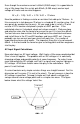
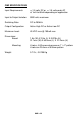
If a circuit contains only simple resistors things are straight forward. For this
discussion we’ll assume C1 is not in the circuit. The only concern is how the
AC voltage is specified. To keep it simple we’ll talk about a voltage that
swings around a zero voltage point and is a simple sine wave. The figure
below shows what this voltage ‘looks’ like.
-170 volts
+170 volts
0 volts