
Instruction manual


OM2 16
Configuring Your OM2
The OM2 is a versatile interface and can be configured to meet the
requirements of many applications. This section describes how to figure out
the necessary set-up and component values for your application. We’ll try to
give you the tools to work with and keep it simple but it is possible that we
may miss something you need to know since not all applications are created
equal.
Input Configuration
DC Input Calculations
The most complex set-up will involve the input circuit even though it looks like
it is very simple. Hang in there and we’ll get you thru it. The main thing to
keep in mind is that it is essential the input current be kept less than 60ma or
the input LED’s may be damaged. Ohm’s Law is the primary tool we’ll use
here. The following calculations assume C2 is bypassed (JMP2 installed) and
are for DC conditions only.
E = I * R
Where:
E = voltage in volts
I = current in amps
R = resistance in ohms
To calculate the circuit current and the resistance required the formulas are:
I = E / R
R = E / I
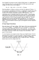
OK, so to calculate the value for R1 and R2 combined we need to figure out
the voltage that will be across R1 and R2 for the input you apply to turn on the
LED. For this we need to know not only the voltage you are applying but also
the voltage that will be across the LED when it is on. This is easy because the
manufacturer of the optical coupler tells us that there will be 1.25 volts across
the LED in the on state. That means that the voltage across R1 and R2 will
be your input voltage, we’ll call it Vin, minus 1.25 volts. The total resistance of
R1 and R2 in series is R1 + R2, we’ll call it Rt, so the formula for their total
resistance is:
Rt = (Vin – 1.25) / I