
Instruction manual


OM2 14
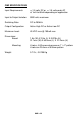
The table below lists suggested values for resistors R1 and R2 based on
some common input signals and we have included resistors for these values
in your OM2 kit. We’ve also provided some extra rows for entry of your own
custom configuration. Because C1 is probably not required for most applica-
tions no values have been provided. The value for C2 is again highly depend-
ant on your application and a value has not been suggested. For many appli-
cations C2 is probably not required. We have provided a 47uF, 16 volt value
as suggested in the schematic. Make sure the voltage rating for C2 is at least
equal to the maximum voltage to be used for +V on the output.
INPUT SIGNAL LEVEL CONFIGURATION
INPUT SIG-
NAL
R1 VALUE R2 VALUE INSTALLED
JUMPERS
110VAC 15K(brown-green-
orange)
15K(brown-green-
orange)
JMP2
220VAC 33K(orange-orange-
orange)
33K(orange-
orange-orange)
JMP2
3VDC 39 (orange-white-
black)
N/A JMP1, JMP2
5VDC 82(gray-red-black) N/A JMP1, JMP2
12VDC 220(red-red-brown) N/A JMP1, JMP2
24VDC 470(yellow-violet-
brown)
N/A JMP1, JMP2
12VAC 330(orange-orange-
brown)
N/A JMP1, JMP2
24VAC 680(blue-gray-
brown)
N/A JMP1, JMP2