
Instruction manual


OM2 11
Make sure the flat side on the component matches+ the printed pattern on the
board for Q 1 and Q2.
14. Install Q1, 2N3904 [2N3904].
15. Install Q2, 2N3904 [2N3904]
16. Install 2 pin header, JMP3 and jumper block
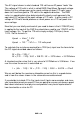
OK… now that we have the basic components installed it’s time to install the
application specific parts. The values indicated in the schematic for R1 and
R2 are for an input voltage of 110VAC. Unfortunately we cannot tell you
exactly what parts you need. You will need to refer to the “Configuring Your
OM2” section of this manual to determine the values for R1 and R2, if you
need C1 or not and if jumpers JP1 and JP2 are required for your application.
Also under consideration is whether or not you need to install C2, and if so
what value do you need. Everything you need to determine what is required is
covered in the “Configuring Your OM2” section. Once you have determined
what your application requires you can then install the following components
as required.