
Instruction manual


DCI1 • 5
CIRCUIT DESCRIPTION
Take a look at the DCI1’s Schematic Diagram as we walk through the circuit
description. We will start with the DTMF audio input and work our way through
to the power supply section.
The DTMF audio input uses a standard style RJ-11 modular phone jack (J6 -
Phone Line Monitor In) for easy interfacing with your phone line or other audio
source (a direct audio pinout for J6 is shown in the wiring section). The input
circuitry near the phone jack allows you to continually monitor the audio signal
and pull off any DTMF data that comes in so it can be decoded. The audio
sniffer formed by C14, C15, R8, R9, and R10 will not capture the line so it does
not interfere with the normal use of your phones. All it does is quietly feed any
audio tones present to the decoder IC for processing. Protection diodes D2 and
D3 limit the incoming signal to +/- 0.7 V so that potentially damaging voltages
like the 90 Vp-p ‘Ring’ signal do not blow up your decoder IC!
The DTMF decoder IC (U3) has the task of monitoring all the input audio
signals from the phone line (or other audio source) and
pulling off any valid audio tones. When a DTMF audio tone is
detected, U3 presents a 4 bit digital code (meaning 0000
through 1111, each position is a bit) to the micro-controller
(U1) that represents which one of the possible 16 different
valid characters it is receiving.
Why a 4 bit code you may ask? Think back to your High
School math class for a moment when you learned about
different base numbering systems. Humans like to work in a
base 10 system (decimal system, deci = 10) using the digits
1 through 10 (or 0 through 9 to be more precise). This is
probably due to the 10 fingers and 10 toes we all learned to
count on as kids. Computers on the other hand (pardon the
pun) like to work with a base 2 numbering system (binary
system, bi = 2) using digits 0 and 1; 0 for off / low and 1 for
on / high. In order to represent the 16 different possible
tones (base 10) you need to have 4 bits in a binary system
2
4
= 1111 (binary) = 16 (decimal). Wow… kind of got off on a
tangent there!
Internally, U3 has a set of counters that latch the 4 outputs
depending on the detected tones. The counters are
referenced to a television color-burst crystal operating at
3.579 MHz (X1) for rock solid measurements. Notice how C1
couples a bit of the X1 crystal frequency over to U1 (the
micro-controller) to set its timing as well.
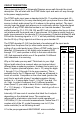
U1 is the pre-programmed 68HC908JK1 micro-controller.
DTMF
Tone
4-bit
Code
1 0001
2 0010
3 0011
4 0100
5 0101
6 0110
7 0111
8 1000
9 1001
0 1010
* 1011
# 1100
A 1101
C 1110
C 1111
D 0000