
Instruction manual


DCI1 • 18
ASSEMBLY INSTRUCTIONS FOR CUSTOM CASE
The enclosure is a key element to the overall pride you will have upon com-
pleting your Ramsey kit. The enclosure will show how you were able to “build
from scratch” a commercial piece of high-tech electronics. For some of us,
the enclosure will also hide a number of “not-so-pretty” assembly mistakes.
Once the kit is enclosed, your friends will never know that you were new to
soldering. Finally, the enclosure case will protect your electronics from many
possible causes of damage so that you can receive years worth of enjoyment
using, talking about, and remembering the fun you had building your kit. In
short, TAKE YOUR TIME
when assembling the enclosure. This is the part that
you and your friends will look at and admire for years!
1. Lay the front and rear plastic plates over their corresponding labels to
verify which sticker goes with which panel. You’ll want to work with one
panel at a time to avoid possible mix-ups.
2. Remove the backing material from one of the stickers and line it up
properly on its pre-punched panel. Make sure that they are aligned cor-
rectly before allowing them to touch the plastic plates. They stick the first
time; line them up right!
3. Use a sharp hobby knife to cut out the holes in the labels along the
pre-punched holes. A short sawing motion from the front side works well
around the inner circumference of the holes.
4. Repeat the above steps for the other panel.
5. Insert the board into the case with the buttons and LEDs extending
through the holes in the front panel.
6. Insert the rear panel into the grooves on the back of the base tray.
7. Secure the PC board to the bottom base tray with 4 short Phillips
head screws.
8. Mount the top cover using the 1” screws after you have completed the
testing phase and final hookup wiring.
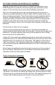
Use of a case set with your DCI1 is highly recommended. The voltage on the
exposed traces near the relay contacts (bottom side of K1 through K4 and the
clamping screws themselves) may be potentially as high as 120 VAC depend-
ing on your target hookup configuration. The added security from using a plas-
tic (non-conductive) enclosure ensures protection from any potentially lethal
voltages.
Great care should be taken with any wiring arrangement to guarantee the
safety of the operator and any others that may come into contact with this unit