DTMF CONTROLLER INTERFACE Ramsey Electronics Model No.
RAMSEY TRANSMITTER KITS • FM100B Professional FM Stereo Transmitter • FM25B Synthesized Stereo FM Transmitter • MR6 Model Rocket Tracking Transmitter • TV6 Television Transmitter RAMSEY RECEIVER KITS • FR1 FM Broadcast Receiver • AR1 Aircraft Band Receiver • SR2 Shortwave Receiver • SC1 Shortwave Converter RAMSEY HOBBY KITS • SG7 Personal Speed Radar • SS70A Speech Scrambler • BS1 “Bullshooter” Digital Voice Storage Unit • AVS10 Automatic Sequential Video Switcher • WCT20 Cable Wizard Cable Tracer • LABC1 L
Ramsey Publication No. MDCI1 Price $5.00 KIT ASSEMBLY AND INSTRUCTION MANUAL FOR DTMF CONTROLLER INTERFACE TABLE OF CONTENTS Introduction ................................. 4 Circuit Description....................... 5 Schematic Diagram .................... 8 Parts Layout Diagram ................. 9 Parts List .................................... 10 Learn As You Build ..................... 11 DCI1 Assembly ........................... 12 Custom Case Assembly ............. 18 Using Your DCI1 ...............
INTRODUCTION The DTMF Controller Interface, or DCI1 for short, was designed to meet the needs of the home automation experimenter. The easy hookup interface and simple operational control lends itself well for a variety of applications. The DCI1 continually monitors your phone line (or just about any other DTMF audio source) and looks for the proper user programmed security code. Once it is heard, the user may select which of the 4 trigger relays to turn on or off.
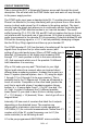
CIRCUIT DESCRIPTION Take a look at the DCI1’s Schematic Diagram as we walk through the circuit description. We will start with the DTMF audio input and work our way through to the power supply section. The DTMF audio input uses a standard style RJ-11 modular phone jack (J6 Phone Line Monitor In) for easy interfacing with your phone line or other audio source (a direct audio pinout for J6 is shown in the wiring section).
This IC contains the developed code required to take the DTMF tone data from U3 and process while reading and writing to FLASH memory, generating the feedback tones, monitoring the programming switch, and turning the relays on and off as needed. Quite a bit for one little part! Since the four relay driver circuits are identical, we’ll walk through the operation of one section and leave it to you to trace out the other three. Take a look at the K1 relay driver circuit on the schematic.
line. Protection diodes D10 and D11 limit the incoming signal on the phone line (between +12.7 and - 0.7 V) so that potentially damaging voltages like the 90 Vp-p ‘Ring’ signal does not blow up Q6! So far we have covered most of the circuitry on the board with exception of the power supply. VR1 and the surrounding parts C3, C4 and the polarity protection diode D1 form a simple voltage regulator to supply a steady 5 VDC to the ICs on the board.
DCI1 • 8
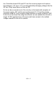
DCI1 PARTS LAYOUT DIAGRAM DCI1 • 9
PARTS SUPPLIED WITH YOUR DCI1 KIT Capacitors 2 22 pF disc capacitor (marked 22) [C7,8] 1 470 pF disc capacitor (marked 470 or 471) [C1] 2 .01µF disc capacitor (marked .01, 103 or 10 nF) [C2,6] 5 .1 µF disc capacitor (marked .
RAMSEY "Learn-As-You-Build KIT ASSEMBLY There are many solder connections on the DCI1 printed circuit board. PLEASE take us seriously when we say that good soldering is essential to the proper operation of your DTMF Controller Interface! • • • Use a 25-watt soldering pencil with a clean, sharp tip. Use only rosin-core solder intended for electronics use. Use bright lighting; a magnifying lamp or bench-style magnifier may be helpful. Do your work in stages, taking breaks to check your work.
DCI1 DTMF CONTROLLER INTERFACE KIT ASSEMBLY Although we know that you are anxious to complete the assembly of your DTMF Controller kit it is best to follow the step-by-step instructions in this manual. Try to avoid the urge to jump ahead installing components. Since you may appreciate some warm-up soldering practice as well as a chance to put some landmarks on the PC board, we’ll first install some of the larger mounting components.
1. Locate and install J1, one of the green 2 screw terminal jacks. The open holes should face outward from the center of the circuit board. These holes are where you will interface your external wiring to the relay contacts. 2. Install J2, one of the green 2 screw terminal jacks. 3. Install J3, one of the green 2 screw terminal jacks. 4. Install J4, the last green 2 screw terminal jack. 5. Identify and install the power connector J5, the 2.1 mm DC power jack at the edge of the PC board.
18. Install R12, a 10K ohm resistor (brown-black-orange). 19. Install R16, a 100 ohm resistor (brown-black-brown). 20. Install R13, a 10K ohm resistor (brown-black-orange). 21. Install R17, a 100 ohm resistor (brown-black-brown). 22. Locate and install K1, one of the large white relays 23. Install relay K2. 24. Install relay K3. 25. Install K4, the last relay.
31. Insert U1, the micro-controller marked with a sticker labeled DCI1 into the socket. Orient the notched end as shown on the PC board silkscreen and Parts Layout Diagram (toward the relays). Before you push it down into the socket, check to be sure none of the pins are bent under or outside of the socket. When you’re sure the pins are where they belong, press the chip down so that it is seated flat within the socket. 32. Install C2, a .01µF ceramic capacitor (marked .01, 103 or 10 nF).
44. Install R3, a 1K ohm resistor (brown-black-red). 45. Install D10, one of the 1N4148 diodes (small glass diode with black band). The lead closest to the black band is the Cathode end. Make sure it lines up with the white band shown on the PC board silkscreen and the Parts Layout Diagram. Be gentle with this fragile part and double check the orientation before soldering. 46. Install D3, another 1N4148 diode in the same fashion as D10. 47. Install D11, another 1N4148 diode. 47.
62. Install S2 the same way. 63. Install J6, the modular RJ-11 phone jack. Pay close attention to the silkscreen and line up the four conductor wires with their respective holes before snapping the part onto the board. Solder all four wire connections being careful not to short them together (they’re really close to each other). Do not solder the plastic posts. The snap fit design will hold it in place. Install LED D9. The flat side is oriented as shown in the diagram.
ASSEMBLY INSTRUCTIONS FOR CUSTOM CASE The enclosure is a key element to the overall pride you will have upon completing your Ramsey kit. The enclosure will show how you were able to “build from scratch” a commercial piece of high-tech electronics. For some of us, the enclosure will also hide a number of “not-so-pretty” assembly mistakes. Once the kit is enclosed, your friends will never know that you were new to soldering.
USING YOUR DCI1 DTMF CONTROLLER INTERFACE Now we’re ready for the moment of truth, the initial power up and running of your DCI1! It’s best to run through the initial power up with nothing wired to the relays just incase you have any build errors. For testing and programming purposes, use a phone next to the DCI1. You will not need to call another phone to work with the system. The unit has built in dial tone and busy tone rejection filters so you can use just one phone to set it up.
Normal Mode Operation: 1. Turn on the unit with power switch S1; Power LED D9 should light up. 2. Lift the phone receiver and press ∗ followed by the 4 digit security code. (The default code is 1, 2, 3, 4 until you change it.) 3. You should hear two quick confirmation tones and the Activity LED should flash twice. • If you enter the code incorrectly you will hear a low frequency error tone and the Activity LED will only flash once. Press ∗ to reset the system and go back to step 2 to try again. 4.
Programming Mode Operation (Setting A New Security Code): NOTE: # and ∗ are special characters and should not be used in your security code except for one special case (more on this below). 1. 2. 3. 4. Turn on the unit with Power switch S1; Power LED D9 should light up. Press in the Program button S2; Activity LED D4 should light up. Lift the phone receiver and press # ; you should hear a confirmation tone.
WIRING AND CUSTOM APPLICATION SUGGESTIONS Using your DCI1 for a variety of applications is very simple. You just need to keep in mind the ratings for the relay contacts listed on the specification page to avoid any problems and use a common sense approach for personal safety.
Typical Low Power AC Wiring: -120 VAC light being switched on Hot side. (Black-Hot) (White-Neutral) Typical High Power Relay: -DCI1 used to trigger another Higher Power relay.
TROUBLESHOOTING GUIDE If your DCI1 does not work at all, recheck the following: • correct orientation of U1 and U3 (see PC board Parts Layout Diagram) • correct polarity of all electrolytic capacitors. • correct orientation of all diodes (especially D1). • all solder connections • jumper wires at all JMP locations. Still having trouble? While we had hoped that it wouldn’t come to this, if you are still having trouble with your DCI1, here are a few additional suggestions.
PROBLEM: The relays seem to get warm when they are on for a while. SOLUTION: This is normal. These 9 VDC relays are rated to work up to almost 12 VDC across their input windings without any problem. The series limiting resistors (R14, 15,16, and 17) keep them well within range over the normal 12 to 15 VDC input operating voltage. Their nominal operating power is about 450 mW so they will get warm to the touch. PROBLEM: It keeps giving me an error tone and it does do what I want.
DCI1 DTMF CONTROLLER INTERFACE SPECIFICATIONS Here are few of the commonly requested specifications for the DCI1: J1, 2, 3, and 4 Relay Outputs - Contact Rating: 5 A, 120 VAC / 28 VDC (Resistive) - Rated Contact Current: 5 A - Max. Contact Capacity: 1250VA AC, 150W DC - Contact Arrangement: SPST-NO - Contact Material: AG Alloy - Note: Not intended for heavily inductive loads such as large motors. J5 Power Input - Input working voltage range: 12 - 15 VDC - Max DCI1 current draw is between 200 - 250 mA.
The Ramsey Kit Warranty Please read carefully BEFORE calling or writing in about your kit. Most problems can be solved without contacting the factory. Notice that this is not a "fine print" warranty. We want you to understand your rights and ours too! All Ramsey kits will work if assembled properly. The very fact that your kit includes this new manual is your assurance that a team of knowledgeable people have field-tested several "copies" of this kit straight from the Ramsey Inventory.
DCI1 DTMF CONTROLLER INTERFACE KIT Quick Reference Page Guide Introduction ............................................4 Circuit Description ..................................5 Schematic Diagram ................................8 Parts List ................................................10 DCI1 Assembly.......................................12 Using Your DCI1 ....................................19 Wiring & Custom Applications ................22 DCI1 Specifications ................................