User Manual IP Information For IP-capable Raloy KVM Switches
Contents 1 Configuration 1-1 Initial Configuration 1-1.1 Setup Fixed IP 1-2 Keyboard, Mouse and Video Configuration 1-2.1 IP Module Keyboard Settings 1-2.2 Remote Mouse Settings 1-2.3 Automatic Mouse Speed and Mouse Synchronization 1-2.4 Host System Mouse Settings 1-2.5 Single and Double Mouse Mode 1-2.6 Recommended Mouse Settings 1-2.7 Video Modes 2 Usage 2-1 Prerequisites 2-2 Login into the IP Module and Logout 2-2.1 Login into the IP Module 2-2.
-4.3 Security 3-4.4 Certificate 3-4.5 Serial Port 3-4.6 Date and Time 3-4.7 Event Log 3-5 Maintenance 3-5.1 Device Information 3-5.2 Event Log 3-5.3 Update FIrmware 3-7.3 Update Firmware 3-5.4 Unit Reset 25 26 28 29 30 32 32 33 33 33 34 4 Troubleshooting 35 5 Frequently Asked Questions 36 6 Addendum 38 A. B. C. D. E. F.
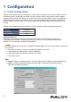
1 Configuration 1-1 Initial Configuration If DHCP mode is enabled (IP auto configuration = DHCP), the IP module will try to contact a DHCP server in the subnet to which it is physically connected. If a DHCP server is found, it may provide a valid IP address, gateway address and net mask. Before you connect the device to your local subnet, be sure to complete the corresponding configuration of your DHCP server. It is recommended to configure a fixed IP assignment to the MAC address of the IP module.
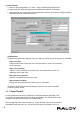
2. Setup Fixed IP c. Setup “IP auto configuration” as “ None” ; setup IP address and Subnet mask d. Enter Super user login and password for Authentication (default : super/pass) e. Click Setup Device. If super login was authenticated, it’ll show “Successfully configured device”. Otherwise it’ll show “Permission Denied”. Authentication To adjust the authentication settings, enter your login as a super user, and change your password. Super user login Enter the login name of the super user.
prompt. Enter “config”, press “Enter” key and wait for a few seconds for the configuration questions to appear. Parameter Value Bits/second 115200 Data bits 8 Parity No Stop bits 1 Flow Control None As you proceed, the following questions will appear on the screen. To accept the default values shown in square brackets below, press “Enter” key. IP auto configuration (none/dhcp/bootp): IP [192.168.1.22]: Net mask [255.255.255.0]: Gateway (0.0.0.0 for none) [0.0.0.
automatically. See the section below for a more detailed explanation. Fixed Mouse Speed This mode just translates the mouse movements from the Remote Console in a way that one pixel move will result in n-pixel moves on the remote system. This parameter n is adjustable with the scaling. Please note that this works only when mouse acceleration is turned off on the remote system. 1-2.
Navigate your mouse pointer into the upper left corner of the applet screen and move it slightly forth and back. Thus the mouse will be resynchronized. If re-synchronizing fails, disable the mouse acceleration and repeat the procedure. 1-2.5 Single and Double Mouse Mode The information above applies to the Double Mouse Mode, where remote and local mouse pointers are visible and need to be synchronized.
2 Usage 2-1 Prerequisites The IP module features an embedded operating system and applications offering a variety of standardized interfaces. This chapter will describe both these interfaces, and the way to use them in a more detailed manner. The interfaces are accessed using the TCP/IP protocol family, thus they can be accessed using the LAN port of the device. The following interfaces are supported: HTTP/HTTPS Full access is provided by the embedded web server.
2-2 Login into the IP Module and Logout 2-2.1 Login into the IP Module Launch your web browser. Direct it to the address of your IP module, which you configured during the installation process. The address used might be an IP address or a domain name, in the case where you have given your IP module a symbolic name in the DNS.
Return to the main page of the IP module. Open the IP module remote console. Exit from the IP module front end. Warning If there is no activity for 30 minutes, the IP module will log you out, automatically. A click on one of the links will bring you back to the login screen. 2-2.2 Logout from the IP Module This link logs out the current user and presents a new login screen. Please note that an automatic logout will be performed if there is no activity for 30 minutes.
2-4 Main Window Starting the Remote Console opens an additional window. It displays the screen content of your host system. The Remote Console will behave exactly in the same way as if you were sitting locally in front of the screen of your remote system. That means keyboard and mouse can be used in the usual way. However, be aware of the fact that the remote system will react to keyboard and mouse actions with a slight delay.
A short description of the options follows. ■■ Monitor Only Toggles the Monitor only filter on or off. If the filter is switched on no remote console interaction is possible, and monitoring is possible. ■■ Exclusive Access If a user has the appropriate permission, he or she can force the Remote Consoles of all other users to close. No one can open the Remote Console at the same time again until this user disables the exclusive access, or logs off.
■■ Video Settings Opens a panel for changing the IP module video settings. IP module features two different dialogs, which for adjusting the video settings. Video Settings through the HTML-Frontend To enable local video port, select this option. This option decides if the local video output of IP module is active and passing through the incoming signal from the host system. The option Noise Filter defines how IP module reacts to small changes in the video input signal.
Vertical Position Use the left and right buttons to move the picture in vertical direction while this option is selected. Reset this Mode Reset mode specific settings (Clock , Phase and Position) to the factory-made defaults. Reset all Modes Reset all settings to the factory-made defaults. Save changes Save changes permanently Undo Changes Restore last settings ■■ Refresh Video Click to run this menu item for retrieving the whole video again from the controlled host and displayed on Remote Console.
■■ Local Keyboard Used to change the language mapping of your browser machine running the Remote Console Applet. Normally, the applet determines the correct value automatically. However, depending on your particular JVM and your browser settings this is not always possible. A typical example is a German localized system that uses an US-English keyboard mapping. In this case you have to change the Local Keyboard setting to the right language, manually. ■■ Hotkeys Opens a list of hotkeys defined before.
Color Depth Set the desired color depth. You may select between 8 or 16 bit for Video Optimized/compression level 0, or between 1 and 8 bit for compression level 1 to 9. The higher the color depth, the more video information has to be captured and to be transferred. Note: If displaying motion pictures on a connection with low speed you may achieve an improvement regarding the video transfer rate by lowering the color depth and disabling the option “Video Optimized”.
3 Menu Options 3-1 Remote Control 3-1.1 KVM Console To open the KVM console, either click on the menu entry on the left, or on the console picture on the right. To refresh the picture, click on the button “Refresh”. 3-1.2 Telnet Console The IP module firmware features a Telnet server that enables a user to connect via a standard Telnet client.
Connecting to the IP module is done as usual and as required by the Telnet client, for instance in a UNIX shell: telnet 192.168.1.22 Replace the IP address by the one that is actually assigned to the IP module. This will prompt for username and password in order to log into the device. The credentials that need to be entered for authentication are identical to those of the web interface.
To change your password, enter the new password in the upper entry field. Retype the password in the field below. Click “Apply” to submit your changes. 3-2.2 Users and Groups The IP module comes with 1 pre-configured user account that has fixed permissions. The account “super” has all possible rights to configure the device and to use all functions IP module offers. Upon delivery, the account “super” has the password “pass”.
limitation in terms of the processing instructions and memory space. To guarantee an acceptable response time we recommend not to exceed the number of 15 users connected to the IP MODULE at the same time. The memory space that is available onto the IP MODULE mainly depends on the configuration and the usage of the IP MODULE (log file entries etc.). That’s why we recommend not to store more than 150 user profiles. 3-3 KVM Settings 3-3.1 User Console The following settings are user specific.
below). Sun Microsystems Java Browser Plugin Instructs the web browser of your administration system to use the JVM of Sun Microsystems. The JVM in the browser is used to run the code for the Remote Console window, which is actually a Java Applet. If you check this box for the first time on your administration system and the appropriate Java plug-in is not already installed on your system, it will be downloaded and installed automatically.
3-3.2 Keyboard / Mouse Host Interface Enables a certain interface the mouse is connected to. You can choose between “Auto” for automatic detection, “USB” for an USB mouse, and “PS/2” for a PS/2 mouse. Warning To use the USB and/or PS/2 interface you need a correct cabling between the managed host and the managing device. If the managed host has no USB keyboard support in the BIOS and you have connected the USB cable only then you will have no remote keyboard access during the boot process of the host.
Mouse Speed ■■ Auto mouse speed Use this option if the mouse settings on host use an additional acceleration setting. The IP module tries to detect the acceleration and speed of the mouse during the mouse sync process. ■■ Fixed mouse speed Use a direct translation of mouse movements between the local and the remote pointer. You may also set a fixed scaling which determines the pixel-amount of the remote mouse pointer movement when the local mouse pointer is moved by one pixel.
When connecting the device directly to legacy Sun computer (with composite sync as the video output, it may be possible that IP MODULE don’t recognize the composite sync automatically. To support signal transmission from a Sun machine, enable this option. If not enabled the picture of the remote console will not be visible. To set the options, click on the button “Apply” 3-4 Device Settings 3-4.1 Network The Network Settings panel as shown below allows changing network related parameters.
Primary DNS Server IP Address IP address of the primary Domain Name Server in dot notation. This option may be left empty, however the IP module will not be able to perform name resolution. Secondary DNS Server IP Address IP address of the secondary Domain Name Server in dot notation. It will be used in case the Primary DNS Server cannot be contacted. Remote Console And HTTPS port Port number at which the IP module’s Remote Console server and HTTPS server are listening.
A freely available Dynamic DNS service (www.dyndns.org) can be used in the following scenario: The IP module is reachable via the IP address of the DSL router, which is dynamically assigned by the provider. Since the administrator does not know the IP address assigned by the provider, the IP module connects to a special dynamic DNS server in regular intervals and registers its IP address there. The administrator may contact this server as well and pick up the same IP address belonging to his card.
Check time The IP module registers itself for initiating the IP address of IP module stored in the Dynamic DNS server at this time. Check interval This is the interval for reporting again to the Dynamic DNS server for updating the IP address associated with the Domain Name of the IP module. Warning The IP module has its own independent real time clock. Make sure the time setting of the IP module is correct. (see the Section called Date And Time) 3-4.
3-4.4 Certificate The IP module uses the Secure Socket Layer (SSL) protocol for any encrypted network traffic between itself and a connected client. During the connection establishment the IP module has to expose its identity to a client using a cryptographic certificate. The default certificate comes with IP MODULE device upon delivery is for testing purpose only. System administrator should not rely on this default certificate as the secured global access mechanism through Internet.
This is the interval for reporting again to the Dynamic DNS server for updating the IP address associated with the Domain Name of the IP module. Warning The IP module has its own independent real time clock. Make sure the time setting of the IP module is correct. (see the Section called Date And Time) Common Name This is the network name of the IP module once it is installed in the user’s network (usually the fully qualified domain name).
Key length This is the length of the generated key in bits. 1024 Bits are supposed to be sufficient for most cases. Longer keys may result in slower response time of the IP module during connection establishment. 3-4.5 Serial Port The IP module Serial Settings allows you to specify what device is connected to the serial port and how to use it. Configuration or console login Do not use the serial port for any special function, use it only for the initial configuration.
giving a new string. Refer to the modem’s manual about the AT command syntax. Modem server IP address This IP address will be assigned to the IP module itself during the PPP handshake. Since it is a point-to-point IP connection virtually every IP address is possible but you must make sure, it is not interfering with the IP settings of the IP module and your console computer. The default value will work in most cases.
3-4.7 Event Log Important events like a login failure or a firmware update are logged to a selection of logging destinations. Each of those events belongs to an event group, which can be activated separately. The common way to log events is to use the internal log list of the IP module. To show the log list, click on “Event Log” on the “Maintenance” page. In the Event Log Settings you can choose how many log entries are shown on each page. Furthermore, you can clear the log file here.
SMTP Logging enabled With this option, the IP module is able to send Emails to an address given by the Email address text field in the Event Log Settings. These mails contain the same description strings as the internal log file and the mail subject is filled with the event group of the occurred log event. In order to use this log destination you have to specify a SMTP server, that has to be reachable from the IP module device and that needs no authentication at all (:).
3-5 Maintenance 3-5.1 Device Information Device Summary This section contains a summary with various information about this IP module and it’s current firmware and allows you to reset the card. The Data file for support allows you to download the IP module data file with specific support information. This is an XML file with certain customized support information like the serial number etc. You may send us this information together with a support request.
3-5.2 Event Log The image above displays the log list including the events that are logged by the IP module. 3-5.3 Update FIrmware 3-7.3 Update Firmware The IP module is a complete standalone computer. The software it runs is called firmware. The firmware of the IP module can be updated remotely in order to install new functionality or special features. A new firmware update is a binary file which will be sent to you by email or which you can download from the supplier web site.
Updating the firmware is a three-stage process: 1. Firstly, the new firmware file is uploaded onto the IP module. In order to do that you need to select the file on your local system using the button “Browse” of the Upload Firmware panel. Once the firmware file has been uploaded, it is checked whether it is a valid firmware file and whether there were any transmission errors. In case of any error the Upload Firmware function will be aborted. 2.
4 Troubleshooting The remote mouse doesn’t work or is not synchronous Make sure the mouse settings in IP module match the mouse model. There are some circumstances where the mouse synchronization process could behave incorrectly, refer to Sections 2.4.1 & 3.5.22 for further explanation. The video quality is bad or the picture is grainy Try to correct the brightness and contrast settings (see Sections 5.4.1 & 6.5.3) until they are out of a range where the picture looks grainy.
5 Frequently Asked Questions The color of remote console displaying a pinkish tint. If you are experiencing the remote control screen displaying a pinkish tint with some graphic cards, please try adjusting the brightness of the remote console by following steps below. 1. Click Video Settings in Options menu of the remote console. 2. Adjust the Brightness setting until the pinkish tint is reduced or eliminated.
How many concurrent user of IP module? The IP module accepts 15 concurrent users. How many bits of connection encrypted of IP module? The IP module provides AES 256 bits connection encrypted. Local mouse and remote mouse didn’t sync after doing mouse Intelligent Sync. Please don’t put window on left-up corner of remote console of IP module. Intelligent Sync has to recalculate the coordinate of mouse from left-up corner on remote console.
6 Addendum A. Key Codes The table below shows the key codes used to defines keystrokes or hotkeys for several functions. Please note that these key codes do not represent necessarily key characters that are used on international keyboards. They name a key on a standard 104 key PC keyboard with an US English language mapping. The layout for this keyboard is shown in the image below.
B. Video Modes The table below lists the video modes IP module supports. Please don’t use other custom video settings besides of these. If done so, IP module may not be able to detect them.
D. IP Module Port Table Port Protocol Purpose Telnet over TCP Web & Telnet Client 80 HTTP over TCP Web 443 HTTPS over TCP Web 443 RFB over TCP Remote Console 443 HTTPS over TCP Drive Redirection 139 SMB over TCP CD-ROM Image (Samba Service) 139 SMB over TCP Floppy disk (Samba Service) 1024 SMB over TCP Samba Service source port 162 SNMP over TCP SNMP trap reception port 1024 SNMP over TCP SNMP source port 443 RFB over TCP Remote Keyboard and Mouse data 23 E.
F. Cable Diagrams VGA Cable: HDB 15-pin Male to Male USB 2.