
User guide

W29C020C
Publication Release Date: April 1999
- 19 - Revision A1
PACKAGE DIMENSIONS
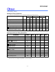
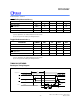
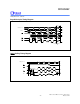
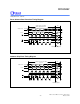
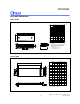
32-pin P-DIP
1.Dimensions D Max. & S include mold flash or
tie bar burrs.
2.Dimension E1 does not include interlead flash.
3.Dimensions D & E1 include mold mismatch and
are determined at the mold parting line.
6.General appearance spec. should be based on
final visual inspection spec.
.
1.371.22
0.0540.048
Notes:
Symbol
Min. Nom. Max. Max.Nom.Min.
Dimension in inches
Dimension in mm
A
B
c
D
e
A
L
S
A
A
1
2
E
0.050 1.27
0.210 5.33
0.010
0.150
0.016
0.155
0.018
0.160
0.022
3.81
0.41
0.25
3.94
0.46
4.06
0.56
0.008
0.120
0.670
0.010
0.130
0.014
0.140
0.20
3.05
0.25
3.30
0.36
3.56
0.555
0.550
0.545 14.1013.9713.84
17.02
15.2414.99
15.49
0.6000.590 0.610
2.29 2.54 2.790.090 0.100 0.110
B
1
1
e
E1
a
1.650 1.660 41.91 42.16
0 15
0.085 2.16
0.6500.630 16.00 16.51
protrusion/intrusion.
4.Dimension B1 does not include dambar
5.Controlling dimension: Inches.
150
Seating Plane
eA
2
A
a
c
E
Base Plane
1
A
1
e
L
A
S
1
E
D
1
B
B
32
1 16
17
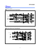
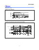
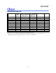
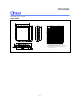
32-pin TSOP
A
A
A
2
1
L
L
1
Y
c
E
H
D
D
b
e
M
0.10(0.004)
θ
Min. Nom. Max. Min. Nom. Max.
Symbol
A
A
b
c
D
E
e
L
L
Y
1
1
2
A
HD
Note:
Controlling dimension: Millimeters
Dimension in Inches
0.047
0.006
0.0410.0390.037
0.007 0.008
0.009
0.005 0.006 0.007
0.720 0.724
0.728
0.311 0.315
0.319
0.780 0.787
0.795
0.020
0.016 0.020
0.024
0.031
0.000 0.004
1
3 5
0.002
1.20
0.05
0.15
1.051.00
0.95
0.17
0.12
18.30
7.90
19.80
0.40
0.00
1
0.20 0.23
0.15 0.17
18.40 18.50
8.00 8.10
20.00 20.20
0.50
0.50 0.60
0.80
0.10
3 5
Dimension in mm
θ
__ __ __ __
__ __
__ __
__ __
__
__
__
__
____