
User guide

W29C020C
- 12 -
AC Characteristics, continued
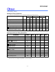
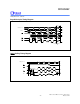
Read Cycle Timing Parameters
(VDD = 5.0V ±10% for 90 nS and 120 nS; VDD = 5.0V ±5% for 70 nS, VSS = 0V, TA = 0 to 70° C)
PARAMETER SYM. W29C020C-70 W29C020C-90 W29C020C-12 UNIT
MIN. MAX. MIN. MAX. MIN. MAX.
Read Cycle Time TRC 70 - 90 - 120 - nS
Chip Enable Access Time TCE - 70 - 90 - 120 nS
Address Access Time TAA - 70 - 90 - 120 nS
Output Enable Access Time TOE - 35 - 40 - 50 nS
CE
High to High-Z Output
TCHZ - 25 - 25 - 30 nS
OE
High to High-Z Output
TOHZ - 25 - 25 - 30 nS
Output Hold from Address change TOH 0 - 0 - 0 - nS
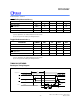
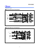
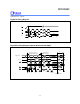
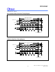
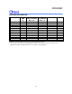
Byte/Page-write Cycle Timing Parameters
PARAMETER SYMBOL MIN. TYP. MAX. UNIT
Write Cycle (erase and program) TWC - - 10 mS
Address Setup Time TAS 0 - - nS
Address Hold Time TAH 50 - - nS
WE
and
CE
Setup Time
TCS 0 - - nS
WE
and
CE
Hold Time
TCH 0 - - nS
OE
High Setup Time
TOES 0 - - nS
OE
High Hold Time
TOEH 0 - - nS
CE
Pulse Width
TCP 70 - - nS
WE
Pulse Width
TWP 70 - - nS
WE
High Width
TWPH 100 - - nS
Data Setup Time TDS 50 - - nS
Data Hold Time TDH 0 - - nS
Byte Load Cycle Time TBLC - - 150 µS
Note: All AC timing signals observe the following guideline for determining setup and hold times:
Reference level is VIH for high-level signal and VIL for low-level signal.