
Instruction Manual


Advance Information W27E520
Publication Release Date: 4/26/2000
- 3 - Revision A1
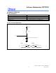
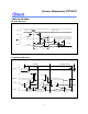
An EPROM's power switching characteristics require careful device decoupling. System designers are
interested in three supply current issues: standby current levels (ISB), active current levels (IDD), and
transient current peaks produced by the falling and rising edges of ALE Transient current magnitudes
depend on the device output's capacitive and inductive loading. Proper decoupling capacitor selection
will suppress transient voltage peaks. Each device should have a
0.1 µF ceramic capacitor connected between its VDD and GND. This high frequency, low inherent-
inductance capacitor should be placed as close as possible to the device. Additionally, for every eight
devices, a 4.7 µF electrolytic capacitor should be placed at the array's power supply connection
between VDD and GND. The bulk capacitor will overcome voltage slumps caused by PC board trace
inductances.
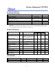
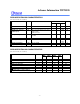
TABLE OF OPERATING MODES
(VPP = 13V, VPE = 13V, VHH = 12V, VDP = 6.5V, VDE = 6.5V, VDD = 5.0V, VDI = 5.0V, X = VIH or VIL)
MODE PIN
ALE
OE
/VPP
OTHER ADDRESS VDD AD[7:0]
Address Latch Enable VIH VIH X VDD A[7:0]
Read VIL VIL AIN VDD DOUT
Output Disable VIL VIH X VDD High Z
Standby VIH VIH AIN VDD A[7:0]
Program VIH VPP AIN VDP DIN
Erase 1 VIH VPE A8&A11 = VIL, A9 = VPE,
A10 = VIH, Others = X
VDE X
Erase 2 VIH VPE First command:
Addr. = 5555 (hex)
VDE AA(hex)
Secon command:
Addr. = 2AAA (hex)
VDE 10(hex)
Product Identifier-
manufacturer
VIL VIL A8 = VIL, A9 = VHH, Others = X VDI DA(Hex)
Product Identifier-device VIL VIL A8 = VIH, A9 = VHH, Others = X VDI 1F(Hex)