
User Manual

Preliminary W27E020
Publication Release Date: December 1997
- 5 - Revision A1
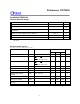
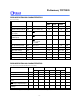
CAPACITANCE
(VCC = 5V, TA = 25° C, f = 1 MHz)
PARAMETER SYMBOL CONDITIONS MAX. UNIT
Input Capacitance CIN VIN = 0V 6 pF
Output Capacitance COUT VOUT = 0V 12 pF
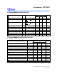
AC CHARACTERISTICS
AC Test Conditions
PARAMETER CONDITIONS
70 nS 90/120 nS
Input Pulse Levels 0 to 3.0V 0.45V to 2.4V
Input Rise and Fall Times 5 nS 10 nS
Input and Output Timing Reference
Level
1.5V/1.5V 0.8V/2.0V
Output Load CL = 30 pF,
IOH/IOL = -0.4 mA/2.1 mA
CL = 100 pF,
IOH/IOL = -0.4 mA/2.1 mA
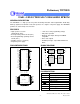
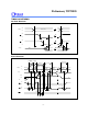
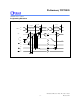
AC Test Load and Waveforms
+1.3V
3.3K ohm
100 pF for 90/120 nS (Including Jig and Scope)
D
(IN914)
OUT
30 pF for 70 nS (Including Jig and Scope)
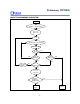
3.0V
0V
1.5V
Test Point Test Point
1.5VFor 70 nS
2.4V
0.45V
2.0V
0.8V
2.0V
0.8V
Test Points Test Points
Input/Output
For 90/120 nS