
Instruction Manual

Preliminary W24L257
Publication Release Date: May 2000
- 3 - Revision A1
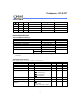
Operating Characteristics, continued
PARAMETER SYM. TEST CONDITIONS MIN. MAX. UNIT
Standby Power Supply
Current
I
SB
CS
= V
IH
(min.) or
Cycle = min. Duty = 100%
-
1
mA
I
SB1
CS
≥
V
DD
-0.2V
- 15 µ
A
Note: Typical parameter is measured under ambient temperature TA = 25
°
C and VDD = 3.3V
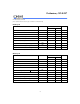
CAPACITANCE
(VDD = 3.3V, TA = 25
°
C, f = 1 MHz)
PARAMETER SYM. CONDITIONS MAX. UNIT
Input Capacitance C
IN
V
IN
= 0V 6 pF
Input/Output Capacitance C
I/O
V
OUT
= 0V 8 pF
Note: These parameters are sampled but not 100% tested.
AC Characteristics
AC Test Conditions
PARAMETER CONDITIONS
Input Pulse Levels 0V to 3.0V
Input Rise and Fall Times 5 nS
Input and Output Timing Reference Level 1.5V
Output Load See the drawing below
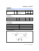
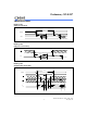
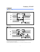
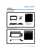
AC Test Loads and Waveform
90%
90%
5 nS
10%
5 nS
10%
OUTPUT
OUTPUT
3.0 V
0 V
100 pF
Including
Jig and
Scope
5 pF
Including
Jig and
Scope
1 TTL
1 TTL
CLZ, OLZ,
CHZ,
OHZ, WHZ, OW
(For T T T T T T )