
User Manual


W24512A
Publication Release Date: March 1999
- 9 - Revision A7
Package Dimensions, continued
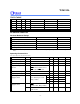
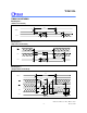
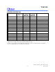
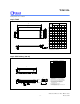
32-pin TSOP
A
A
A
2
1
L
L1
Y
c
E
H
D
D
b
e
M
0.10(0.004)
θ
Min. Nom. Max.
Min.
Nom.
Max.
Symbol
A
A
b
c
D
E
e
L
L
Y
1
1
2
A
H
D
Note:
Controlling dimension: Millimeter
Dimension in Inches
0.047
0.006
0.041
0.039
0.037
0.007 0.008
0.009
0.005 0.006
0.007
0.720 0.724
0.728
0.311 0.315
0.319
0.780 0.787
0.795
0.020
0.016 0.020
0.024
0.031
0.000 0.004
1
3 5
0.002
1.20
0.05
0.15
1.051.00
0.95
0.17
0.12
18.30
7.90
19.80
0.40
0.00
1
0.20 0.23
0.15 0.17
18.40 18.50
8.00 8.10
20.00 20.20
0.50
0.50 0.60
0.80
0.10
3 5
Dimension in mm
θ
__
__
__
__
__
__
__
__
__
__
__
__
__
__
____
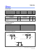
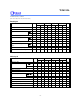
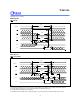
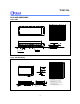
32-pin P-DIP Skinny (300 mil)
e
A
A
a
c
E
Base Plane
Mounting Plane
1
A
1
e
L
A
S
1
E
D
1
B
B
1
2
16
17
32
1. Dimension D Max. & S include mold flash or
tie bar burrs.
2. Dimension E1 does not include interlead flash.
3. Dimension D & E1 include mold mismatch and
are determined at the mold parting line.
6. General appearance spec. should be based on
final visual inspection spec.
1.631.47
0.0640.058
Notes:
Symbol
Min. Nom. Max. Max.Nom.Min.
Dimension in Inches
Dimension in mm
0.060 1.52
0.200
5.08
0.015
0.145
0.016
0.150
0.018
0.155
0.022
3.68
0.41
0.38
3.81
0.46
3.94
0.56
0.008
0.120
0.470
0.010
0.130
0.014
0.140
0.20
3.05
0.25
3.30
0.36
3.56
11.94
2.29 2.54 2.790.090 0.100
0.110
A
B
c
D
e
A
L
S
A
A
1
2
E
B
1
1
e
E1
a
0
0.065
1.65
0.450
0.430 10.92
11.43
15
°
0
°
4. Dimension B1 does not include dambar
protrusion/intrusion.
5. Controlling dimension: Inches.
1.60 1.62 40.64 41.15
0.286
0.295
0.290
0.315
0.294
0.335
7.26
7.49
7.36
8.00
7.46
8.50
15