
User Manual


W24512A
- 8 -
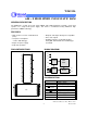
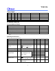
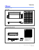
PACKAGE DIMENSIONS
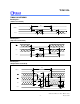
32-pin SOJ
D
H
B
b
e
e
1
16
17
32
E
Y
A
A
A
Seating Plane
c
L
S
θ
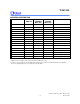
Symbol
Dimension in mmDimension in Inches
Min. Nom.
Max.
Min. Nom.
Max.
A
A
A
B
b
c
D
E
e
e
H
L
S
Y
0.140
0.020
0.095 0.100 0.105
0.0320.0280.026
0.0220.0180.016
0.0140.010
0.008
0.8350.825
0.305
0.3000.295
0.0560.0500.044
0.2870.2670.247
0.3450.3350.325
0.080
0.045
0.004
0 10
0.815
3.556
0.508
2.413
2.540 2.667
0.8130.7110.660
0.559
0.4570.406
0.356
0.2540.203
21.20920.955
7.7477.6207.493
1.4221.2701.118
7.2906.7826.274
8.7638.509
8.255
2.032
1.143
0.102
0
°
10
°
20.701
θ
__
__
__
__
__
__
__
__
__
__
__
__
__
__
__
__
__
__ __
__
__
__
1
2
1
e
e
1
2
1
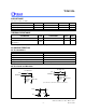
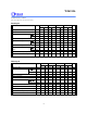
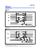
32-pin SO Wide Body
1
17
32
16
y
e
D
S
Seating Plane
b
A
A
E
H
L
L
E
E
1
c
e
1
1
e
A
2
See Detail F
Detail F
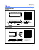
1. Dimension D Max. & S include mold flash
or tie bar burrs.
2. Dimension b does not include dambar
protrusion/intrusion.
3. Dimension D & E include mold mismatch
and are determined at the mold parting line.
.
Notes:
4. Controlling dimension: Inches.
5. General appearance spec should be based
on final visual inspection spec.
0.200.15
0.0080.006
Symbol
Min.
Nom.
Max. Max.
Nom.
Min.
Dimension in Inches
Dimension in mm
A
b
c
D
e
HE
L
y
A
A
L
E
1
2
E
0.012 0.31
0.118
3.00
0.004
0.101
0.014
0.106
0.016
0.111
0.020
2.57
0.36
0.10
2.69
0.41
2.82
0.51
0.047
0.004
0
10
0.805
0.055
0.817
0.063 1.19
20.45
1.40
20.75
1.60
0.556
0.5560.546 14.3814.1213.87
10
0
0.10
11.43
11.30
11.18
0.4500.4450.440
0.58 0.79 0.99
0.023
0.031
0.039
1.12 1.27 1.420.044 0.050
0.056
S
0.91
0.036
θ