
User guide

5
U2741B
4733A–RKE–11/03
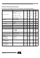
Output Power
Measurement
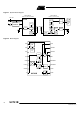
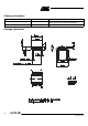
The output network [as shown in Figure 4] can be used for output power evaluation, the
exact values of L
10
and C
10
depend on the layout.
L
10
and C
10
form the transformation network to adopt the output impedance of the IC to
50
W. Table 1 shows the values for an output power of 2 mW and an R
PWRSET
= 1.2 kW.
Figure 4. Measurement Output Network
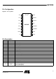
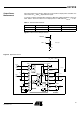
Figure 5. Application Circuit
Table 1. Transformation Network
f/MHz C10/pF L10/nH Z
Load_opt
/W
315 2.7 56 260 + j330
433.92 1.8 33 185 + j268
PWRVCC
ANT
V
S
L
10
C
10
50 W
Z
Load-opt
161
2
3
4
5
6
7
8
15
14
13
12
11
10
9
64
f
PA
n
f
OR
Power
up
VCO
XTO
ASK
FSK
VCC
CLK
GND
LFVCC
LFGND
LF
DIVC
PWRSET
PWRVCC
ANT
PWRGND1
PWRGND2
XTO1
XTO2
C
5
R
PWRSET
L
Feed
C
Loop1
13.56 MHz
C
3
C
4
+V
S
= 2.0 ... 5.5 V
C
Loop2
C
7
C
1
C
2
R
4
ASK
FSK
CLK
3.39 MHz
C
6
U2741B
Antenna