
User guide

15
TS81102G0
2105C–BDC–11/03
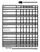
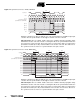
Notes: 1. TCPD is tuned with DMUXDelAdjCtrl: TCPD = 981 ± 250 ps.
2. TCPD is tuned with DMUXDelAdjCtrl: TCPD = 1084 ± 250 ps.
3. TSSR depends on DMUXDelAdjCtrl: TSSR = -580 ± 250 ps. TSSR < 0 because of Clock Path internal delay.
4. TSSR depends on DMUXDelAdjCtrl: TSSR = -477 ± 250 ps. TSSR < 0 because of Clock Path internal delay.
5. THSR depends on DMUXDelAdjCtrl: THSR = 780 ± 250 ps.
6. THSR depends on DMUXDelAdjCtrl: THSR = 677 ± 250 ps.
7. TSCKIN depends on DMUXDelAdjCtrl: TSCKIN = -794 ± 250 ps. TSCKIN < 0 because of Clock Path internal delay.
8. TSCKIN depends on DMUXDelAdjCtrl: TSCKIN = -691 ± 250 ps. TSCKIN < 0 because of Clock Path internal delay.
9. THCKIN depends on DMUXDelAdjCtrl: THCKIN = 994 ± 250 ps.
10. THCKIN depends on DMUXDelAdjCtrl: THCKIN = 891 ± 250 ps.
11. TOD depends on DMUXDelAdjCtrl: TOD = 1820 ± 250 ps. TOD is given for ECL 50Ω/2 pFoutput load.
12. TOD depends on DMUXDelAdjCtrl: TOD = 1717 ± 250 ps. TOD is given for ECL 50Ω/2 pFoutput load.
13. TPD is the number of Clkln clock cycle from selection of Port A to selection of Port H in 1:8 conversion mode, and from
selection of Port A to selection of Port D in 1:4 conversion mode. It is the maximum number of Clkln clock cycle, or pipeline
delay, that a data has to stay in the DMUX before being sorted out. This maximum delay occurs for the data sent to Port A.
For instance, the data sent to Port H goes directly from the input to the Port H, and its pipeline is 0. But even for this data,
there is an additional delay due to physical propagation time in the DMUX.
14. TROD and TFOD are given for ECL 50Ω/2 pF output load. In TTL mode, the TROD and TFOD are twice the ones for ECL.
(For other termination topology, apply proper derating value 50 ps/pF in ECL, 100 ps/pF in TTL mode.)
15. TDRF depends on DMUXDelAdjCtrl: TDRF = 1856 ± 250 ps. It is given for ECL 50Ω/2 pF output load.
16. TDRF depends on DMUXDelAdjCtrl: TDRF = 1753 ± 250 ps. It is given for ECL 50Ω/2 pF output load.
17. TDRR depends on DMUXDelAdjCtrl: TDRR = 1858 ± 250 ps. It is given for ECL 50Ω/2 pF output load.
18. TDRR depends on DMUXDelAdjCtrl: TDRR = 1725 ± 250 ps. It is given for ECL 50Ω/2 pF output load.
19. TARDR is given for ECL 50Ω/2 pF output load.
20. TSRDR is given for ECL 50Ω/2 pF output load. It is minimum value since RstSync clock is synchronized with Clkln clock.
21. TRDR and TFDR are given for ECL 50Ω/2 pF output load.
22. THBIST depends on the configuration of the DMUX. There must be enough Clkln clock cycles to have all the 512 codes,
(see different Timing Diagrams).
23. With transmission line (ZO = 50Ω) and output load R = 50Ω; C = 2 pF.
24. Without output load.
25. With transmission line (ZO = 50Ω) and output load R = 50Ω; C = 2 pF.
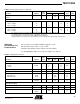
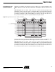
Setup time from Bist to Clkln TSBIST – – 1000 – ps
Rise/fall time for (10% – 90%) TRBIST/
TFBIST
– 1000 – – ps
ADC Delay Adjust
Input frequency FMADA – 2 – 2.2 GHz
Input pulse width (high) TC1ADA – 90 – – ps
Input pulse width (low) TC2ADA – 90 – – ps
Input rise/fall time TRIADA/
TFIADA
–
100
100
150
150
–
–
ps
Output rise/fall time TROADA/
TFOADA
–
–
–
145
104
–
–
ps
(23)
Data output delay (typical delay adjust setting)
TADA –
–
–
784
896
–
–
ps
(24)
(25)
Output delay drift with temperature TADAT – – 2.5 – ps/°C
Output delay uncertainly JITADA – – 30 – ps
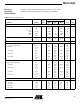
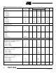
Table 5. Switching Performances (Continued)
Parameter Symbol
Test
Level
Value
Unit NoteMin Typ Max