
Manual


TIMING DIAGRAMS
Readout Mode
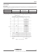
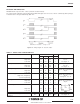
The serial readout register is operated in a two phase transfer mode. However, there are provided 6 separated command
electrodes that shall be connected differently depending on the required readout mode. The following table gives the con-
nections to be made for each mode:
Readout modes Ü 1 output, VOS1 1 output, VOS2 2 outputs (parallel)
Drive clocks (signals) Þ (mirror effect)
FL1 pins B2, B3, B1 pins B2, A3, A1 pins B2, B3, A1
FL2 pins A2, A3, A1 pins A2, B3, B1 pins A2, A3, B1
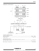
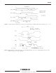
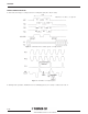
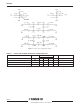
The following diagrams are given for 20 MHz readout frequency, 1.25 MHz vertical transfer frequency
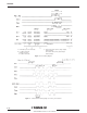
Figure 3 : Frame timing diagram
5/16
TH7888A