
Manual


PELTIER OPTION
Storage temperature ..............................................................................................................................................-55°C to +85°C
Operating temperature...........................................................................................................................................-40°C to +70°C
Thermal cycling...............................................................................................................................................................10°C / mn
Maximum applied voltages :
PIN MAX VOLTAGE RANGE MAX CURRENT RANGE
AA1, AA2 with respect to Y1, Y2 5 V 1.8 A
Stresses above those listed under absolute maximum ratings may cause permanent device failure. Functionality at or abo-
ve these limits is not implied. Exposure to absolute maximum ratings for extended periods may affect device reliability.
Operating range defines the limits whithin which the functionality is guaranteed.
Electrical limits of applied signals are given in operating conditions section
OPERATING PRECAUTIONS
Shorting the video outputs to any other pin, even temporarily, can permanently damage the on-chip output amplifier.
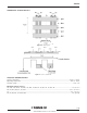
OPERATING CONDITIONS
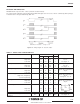
TABLE1-DC CHARACTERISTICS
PARAMETER SYMBOL VALUE UNIT
Min. Typ. Max.
Output amplifier drain supply VDD1, VDD2 14.5 15 15.5 V
Protection drain bias VDP 14.5 15 15.5 V
Reset bias VDR 14.5 15 15.5 V
Antiblooming diode bias VA 14.5 15 15.5 V
Register output gate bias VGS 2.2 2.5 2.8 V
Output amplifier source supply VS1,2 0 V
Ground * VSS 0 V
OPTIONAL
Peltier power supply ** I
PELTIER
1.1 A
Voltage accross Peltier V
PELTIER
3V
* Ground : note that the package metal back is internally grounded.
** Peltier power supply : conditions for 10°C sensor temperature with 50°C external temperature.
4/16
TH7888A