
User guide

7
TH7887A
2146A–IMAGE–05/02
Absolute Maximum Ratings*
Operating Range
The operating range defines the limits where function is guaranteed.
Electrical limits of applied signals are given in the operating conditions section.
Operating
Precautions
Shorting the video outputs to any other pin, even temporarily, can permanently damage
the on-chip output amplifier.
Operating Conditions
Storage Temperature .................................... -55°Cto+150°C
*NOTICE: Stresses above those listed under absolute max-
imum ratings may cause permanent device fail-
ure. Functionality at or above these limits is not
implied. Exposure to absolute maximum ratings
for extended periods may affect device reliability.
Operating Temperature............................... -40°Cto+85°C
Thermal Cycling.........................................................15°C/mm
Maximum Applied Voltages:
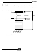
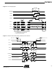
A2, A6, B2, C5, B5, C3, A5, C2, A3, A7, B7, C4
B4, C6, C7, A4, V7, W8, V8, AA8, V6, AA5..........-0.3V to 15V
V2,V3,V4,V5,W2,W3,W4,W5
W6, C1, AA6 ......................................................-0.3V to 15.5V
C8 .........................................................................-0.3V to 12V
AA7, V1, W1, W7, A8, B8, B6, B1, A1, B3 ............. Ground 0V
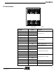
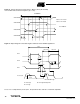
Table 1. DC Characteristics
Parameter Symbol
Value
UnitMin Typ Max
Output amplifier drain supply
VDD1, VDD2,
VDD3, VDD4
14.5 15 15.5 V
Screen voltage VDDP 14.5 15 15.5 V
Reset bias VDR 14.5 15 15.5 V
Antiblooming diode bias VA 14.5 15 15.5 V
Register output gate bias VGS 2.2 2.5 2.8 V
Output amplifier source supply VS1,2,3,4 – 0 – V
Ground VSS – 0 – V