
User Manual

8
TH7841A
1998A–IMAGE–05/02
Note: 1. Drain supply current I
DD
decreases from 10 mA to 8 mA typically when internal sampling clock is disabled (V
INH
=V
DD
=
15V).
Insertion of a serial resistor (typically 100Ω) at the driver output avoids spurious negative transients.
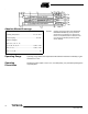
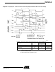
Table 6. Selection of Operating Modes
Option Implementation Note
No Sampling
Φ
ECHA
(3) and Φ
ECHB
(25) Connected to VDD
S
Φ
ECHA
(4) and SΦ
ECHB
(24) Unconnected
V
INH
(16) Connected to V
DD
(1)
Sampling By External Clocks
Sampling Clocks Connected to
Φ
ECHA
- Φ
ECHB
SΦ
ECHA
and SΦ
ECHB
Unconnected
V
INH
(16) Connected to V
DD
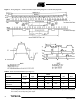
See Figure 4 for sampling
clock timing
(1)
Reset Control By External Clocks
Ext.
Φ
RA
on Φ
RA
(5) Input
Ext.
Φ
RB
on Φ
RB
(21) Input
SeeFigure4for
reset clock timing
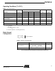
Table 7. External ΦRA, ΦRB, ΦECHA, ΦECHB Clocks Characteristics
Parameter Symbol Logic
Values
UnitMin Typ Max
External Reset Clock
Sampling Clock
Φ
RA
, Φ
RB
,
Φ
ECHA
, Φ
ECHB
High 12 13 14 V
Low 0.0 0.4 0.6 V
Reset And Sampling Clock
Capacitance
C
Φ
RA
CΦ
RB
CΦ
ECHA
CΦ
ECHB
10 15 pF