
User Manual

3
TH7841A
1998A–IMAGE–05/02
Operating Conditions (T = 25°C)
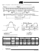
Notes: 1. It is recommended to maintain V
DR
at V
DD
-2V.
2. V
T
nominal =
3. No use for operation – For testing purpose only.
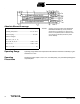
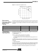
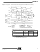
Basic Internal
Configuration
Note: 1. Make the straps as short as possible to avoid any parasitic coupling to these connec-
tions. The load capacitance introduced by the strap should not exceed 5 pF.
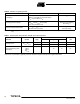
Table 1. DC Characteristics
Parameter Symbol
Values
Unit NoteMin Typ Max
Output Amplifier Drain Supply V
DD
14 15 16 V
Reset DC Bias V
DR
12 13 14.5 V
(1)
Output Gate DC Bias V
GS
5.566.5V
Photosensitive Zone and
Register DC Bias
V
T
66.57 V
(2)
Substrate Bias V
SS
0.0 0.0
Te s t Poi n t 1 T P1 V
DD
V
(3)
Test Points 2 and 3 TP2, TP3 V
SS
V
(3)
VΦ
T
()high VΦ
T
()low+
2
------------------------------------------------------------ 5%±
SΦ
ECHA
and Φ
RA
internal to TH7841A
SΦ
ECHB
and Φ
RB
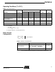
Table 2. Selection of Nominal Mode
Option Implementation Note
Internal Sampling
V
INH
(16) Connected to V
SS
SΦ
ECHA
(4) and Φ
ECHA
(3) Strapped
SΦ
ECHB
(24) and Φ
ECHB
(25) Strapped
(1)
Internal Reset Φ
RA
(5) and Φ
RB
(21) Connected to VDD