
User Manual

87
T89C51AC2
Rev. B – 19-Dec-01
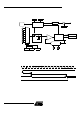
Each of the i nte rrup t sources can be individually enabled or disabled by setting or clear-
ing a bit in the Interrupt Enable regi s ter. T his register a lso contains a glo bal disable bit
which m us t be cleared to disable all the interrupts at the same tim e.
Each interrupt sourc e can also be i ndividually programmed to one of fou r pri ority levels
by s etting or clearing a bit in the Inte rrup t Priority registers. The Table below shows the
bit values and priority levels associated with each combination.
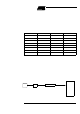
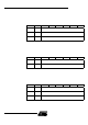
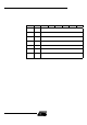
Table 49. Pri ority Level Bit V alues
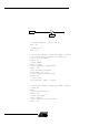
A low-priorit y i nterru pt can be inte rrupt ed by a high priority interrupt but no t by ano th er
low-priority i nterrup t. A high-priority interrupt can not be interrupted by any other interrupt
source.
If two i nterrupt requests of different priority le vels are recei ved sim ultaneous ly, the
reques t of the higher priori t y lev el is se r v iced. If int errupt requests of the s ame priority
level are received simultaneously , an internal polling sequence determines which
request is serviced. Thus within each priority level there is a second priority struc ture
de termined by the po lling sequence, see Table 50.
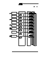
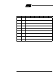
Table 50. Interrupt pri ority Within level
IPH.x IPL.x Interrupt Level Priority
0 0 0 (Lowest)
011
102
1 1 3 (Highest)
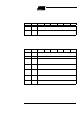
Interrupt Name Interrupt Address Vector Priority Number
external interrupt (INT0) 0003h 1
T imer0 (TF0) 000Bh 2
external interrupt (INT1) 0013h 3
T imer1 (TF1) 001Bh 4
PCA (CF or CCFn) 0033h 5
UART (RI or TI) 0023h 6
T imer2 (TF2) 002Bh 7
ADC (ADCI) 0043h 9