
User Manual

86
T89C51AC2
Rev. B – 19-Dec-01
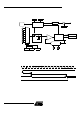
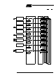
17. Interrupt System The controller has a total of 8 i nterrupt vectors: tw o extern al interrupts (INT0 and INT1),
three timer i nterrupts (timers 0, 1 and 2), a serial port interrupt, a PCA, a timer over run
interrupt and an ADC. These interrupts are s hown below .
Figure 40. Int errupt Control System
EX0
IEN0.0
00
01
10
11
External
Interrupt 0
INT0#
EX1
IEN0.2
External
Interrupt 1
INT1#
ET0
IEN0.1
Timer 0
EC
IEN0.6
PCA
ET1
IEN0.3
Timer 1
ES
IEN0.4
UART
EADC
IEN1.1
AtoD
Converter
Interrupt Enable Lowest Priority Interrupts
Highest
Priority Enable
00
01
10
11
00
01
10
11
00
01
10
11
00
01
10
11
00
01
10
11
00
01
10
11
Priority
Interrupts
AIN1:0
Timer 2
00
01
10
11
ET2
IEN0.5
TxD
RxD
CEX0:5