
User Manual

84
T89C51AC2
Rev. B – 19-Dec-01
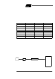
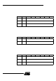
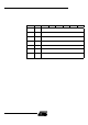
16.9 Register s Table 44. ADCF Register
ADCF (S:F6h)
ADC Configuration
Rese t Va lue=0000 0000b
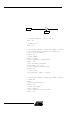
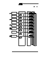
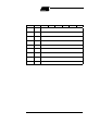
Table 45. ADCON Register
ADCON (S:F3 h)
ADC Control Regi s ter
Rese t Va lue=X000 0000b
76543210
CH 7 CH 6 CH 5 CH 4 CH 3 CH 2 CH 1 CH 0
Bit
Number
Bit
Mnemonic Description
7-0 CH 0:7
Channel Configuration
Set to use P1.x as ADC input.
Clear to use P1.x as standart I/O port.
76543210
- PSIDLE ADEN ADEOC ADSST SCH2 SCH1 SCH0
Bit
Number
Bit
Mnemonic Description
7-
6 PSIDLE
Pseudo Idle mode (best precision)
Set to put in idle mode during conversion
Clear to convert without idle mode.
5ADEN
Enable/Standby Mode
Set to enable ADC
Clear for Standby mode (power dissipation 1 uW).
4ADEOC
End Of Conversion
Set by hardware when ADC result is ready to be read. This flag can generate an
interrupt.
Must be cleared by software.
3 ADSST
Start and Status
Set to start an A/D conversion.
Cleared by hardware after completion of the conversion
2-0 SCH2:0
Selection of channel to convert
see Table 43