
User Manual


80
T89C51AC2
Rev. B – 19-Dec-01
16. Analog-to-Digit al
Converter (ADC)
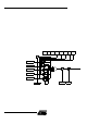
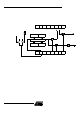
This sect ion des cribes the on-ch ip 10 bit an alog-to-digi tal converter of the T89C51A C2.
Eight ADC cha nnels are available for s ampling of the ex t ernal sources AN0 t o AN7. A n
analog multiplexer allows t he single ADC convert er to select one from the 8 ADC chan-
nels as ADC input voltage (ADCIN). ADCIN is converted by the 10 bit-cascaded
potentiometric ADC.
Two kind of conversion are available:
- S tand ard conv ers ion (8 bits).
- Precision conversion (10 bits).
For the preci s ion conv ers ion, se t bi t PS IDL E in ADCON re gister and start convers ion.
The dev ice i s in a ps eudo-idle m ode, the CPU does not run but the peripherals are
always running. This mode allows d igital noise to be as low as possible, to ensure high
precision conversi on.
For this mode it i s neces s ary to work with end of conv ers ion interrupt, which is th e only
way t o wake the device up.
If another interrupt occurs during the precision conversion, it w ill be treated only after
this conversion is ended.
16.1 Features • 8 channels with multiplexed inputs
• 10-bit cas caded potentiometric ADC
• Conv ers ion time 16 micro-seco nds (t y p.)
• Zero Error (offset) +/- 2 LSB max
• Po sitive E xternal R eference Voltage Range (V RE F) 2.4 to 3.0Volt (typ.)
• ADCINRange0to3Volt
• Integral non-linearity ty pical 1 LS B, max. 2 LSB
• Differential non-linearity typical 0.5 LSB, max. 1 LSB
• Conv ers ion Complete Flag or Conv ersion Com plete Interrupt
• Se lectable ADC Clock
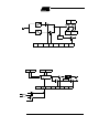
16.2 ADC Port1 I/O
Functions
Port 1 pi ns are general I/O that are s hared with th e ADC chan nels. T he channel select
bit in ADCF register define which ADC channel/port1 pin will be used as ADCIN. The
remain ing ADC channel s/port1 pins can be used as general purpose I/O or as t he alter-
nate function that is available.
A conversio n launched on a channel which are not selected on ADCF regist er will not
have any effect.